Testing a Content-Delivery System

a content delivery and system technology, applied in the field of testing a content delivery system, can solve the problems of impracticality of monitoring all the oob signals across different plants, and problems that were usually realized

Active Publication Date: 2010-12-09
COMCAST CABLE COMM LLC
View PDF8 Cites 23 Cited by
  • Summary
  • Abstract
  • Description
  • Claims
  • Application Information

AI Technical Summary

Benefits of technology

The patent describes a process and system for monitoring and testing a control channel in a content-delivery network. This involves joining a connection with the control channel, decoding the content of a signal in the control channel, and checking if it complies with a pre-determined rule. The system can also identify network elements associated with the decoded content and conduct tests to verify their integrity. The patent also describes a graphical user interface for displaying the testing status and results of a control channel. The technical effects of this patent include improved monitoring and testing of control channels in content-delivery networks, which can help to ensure the safe and reliable delivery of content to users.

Problems solved by technology

The technical problem addressed in this patent text is the need for a common platform on which interactive services can be deployed in a cable network. The text describes the challenges faced in the past with a proprietary operating system software and the development of the OpenCable initiative to standardize the operating systems of electronics that connect to the network. The text also discusses the key changes made in the Tru2way specification to affect the command and control transport mechanism between the set-top box and the headend. The text highlights the benefits of the DSG specification in consolidating control traffic and offering opportunities to monitor and test control channel signals.

Method used


Image

  • Testing a Content-Delivery System
  • Testing a Content-Delivery System
  • Testing a Content-Delivery System

Examples


Embodiment Construction

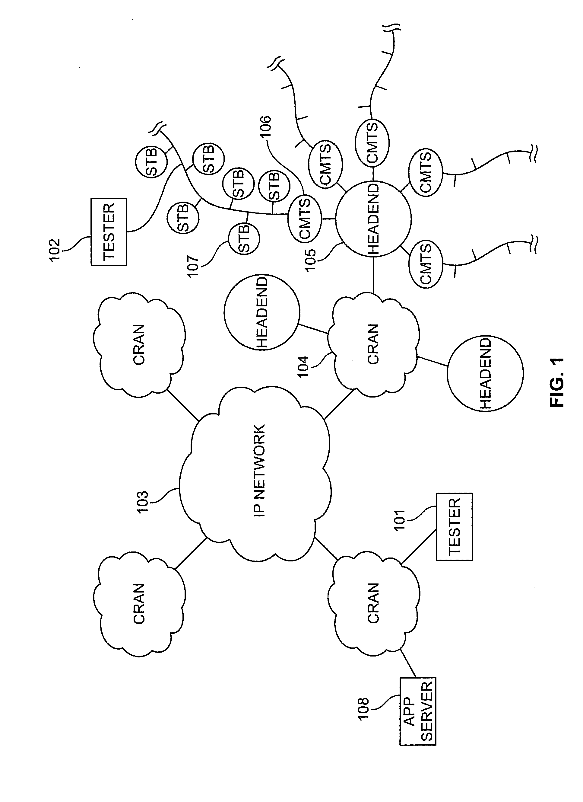
[0025]FIG. 1 shows a schematic of one embodiment of a content-delivery network 100 incorporating the testing apparatus 101, 102 of the disclosure. Throughout this disclosure, reference is made to a cable system embodiment of the network 100; however, it should be understood the system and method of the disclosure are not limited to a cable system and may include any content-delivery network, e.g., Internet-based systems, wireless systems, and fiber-based systems. As used herein, a content delivery network or content distribution network (“CDN”) is a system of computers networked together that cooperate to deliver content to end users or subscribers.

[0026]Referring to FIG. 1, the network 100 comprises an IP network (backbone) 103. IP network 103 may comprise a large collection of interconnected, high-capacity data routes and core routers. Networked to IP network 103 may be a plurality of subnetworks 104, which, in a cable system may include a Converged Regional Area Networks (CRAN), ...


PUM


Abstract

A content delivery networked is monitored to verify operation of control channels for the delivery of content to a customer. Monitoring includes joining a connection with at least one control channel in the network, decoding content of a signal in the control channel, determining whether the decoded content complies with a pre-determined rule corresponding to content transmitted in the control channel, and producing a report indicating whether the decoded content is compliant with the rule. In addition, a graphical user interface (GUI) displays the status and results of testing the control channel. The GUI is configured to perform generating a display representing testing status of a plurality of DSG tunnels in a first frame and test results of the DSG tunnels in a second frame and providing details of a DSG tunnel test when selected by a user.

Description


Claims


Application Information

Patent Timeline
Owner COMCAST CABLE COMM LLC
Why Eureka
Try Eureka