Eureka AIR delivers breakthrough ideas for toughest innovation challenges, trusted by R&D personnel around the world.

Decorative molding trimming system and method of installing

a molding and decorative technology, applied in the field of methods and methods, can solve the problems of time-consuming molding application, skilled carpentry, and often required skilled labor to properly install crown molding

Inactive Publication Date: 2010-12-16
PAIDAR REZA +1
View PDF13 Cites 15 Cited by
  • Summary
  • Abstract
  • Description
  • Claims
  • Application Information

AI Technical Summary

Benefits of technology

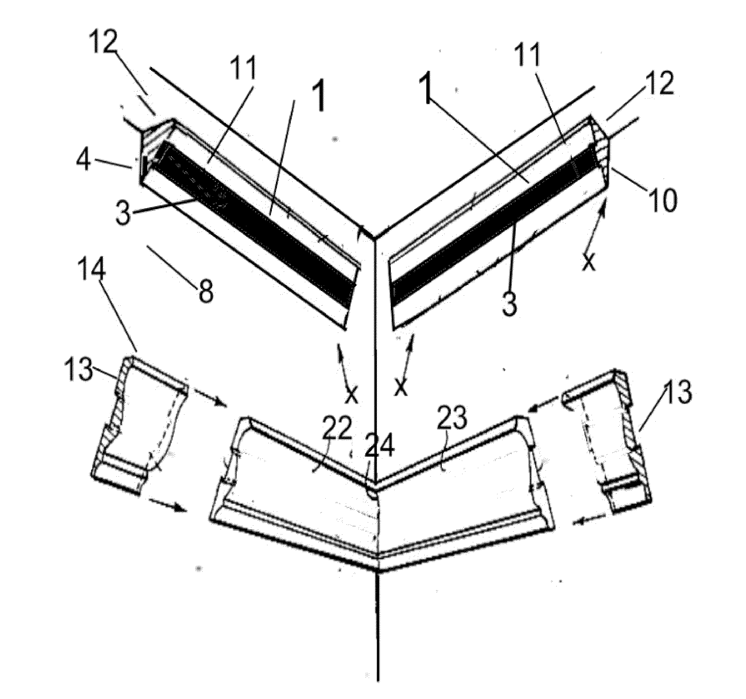
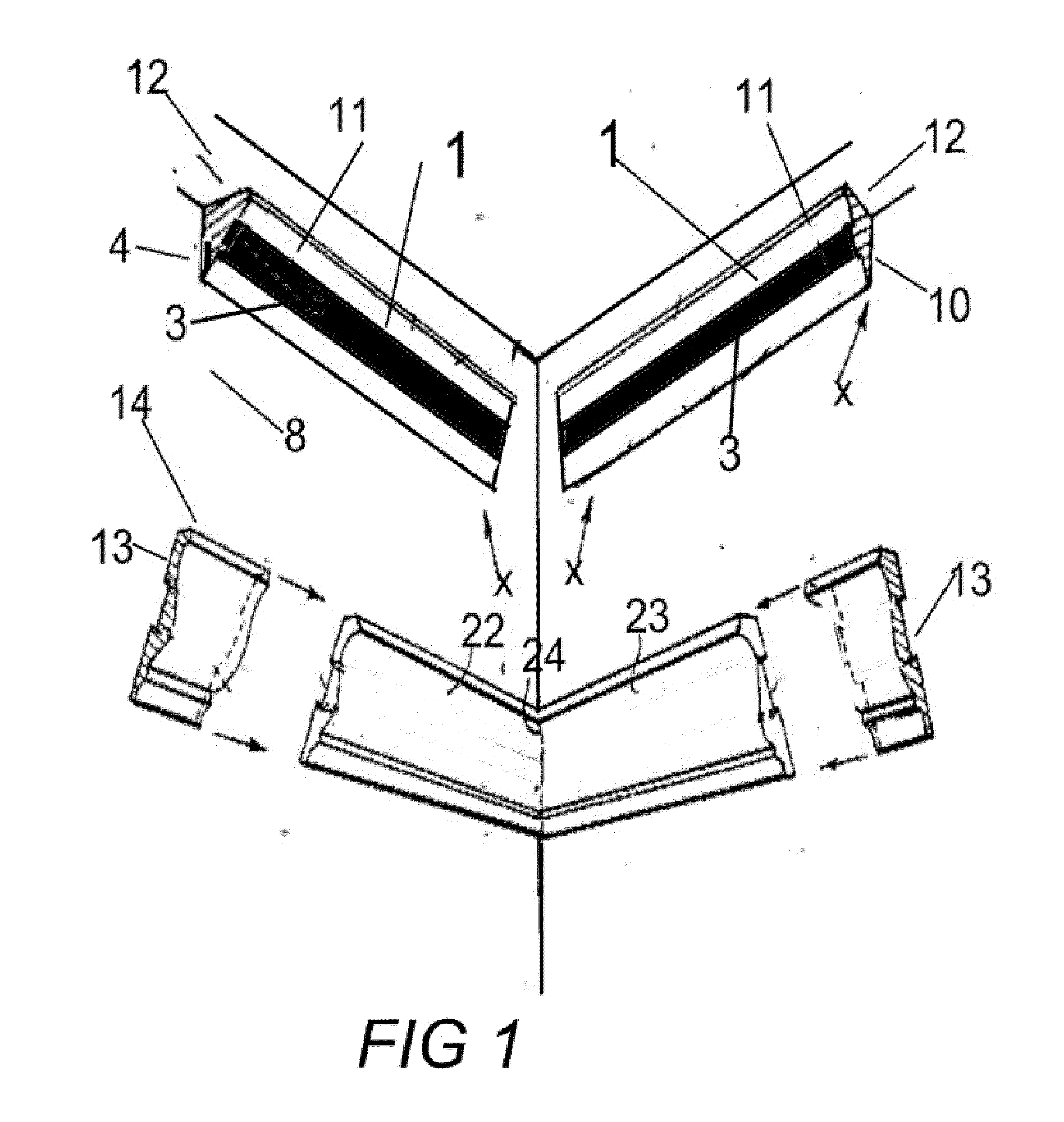
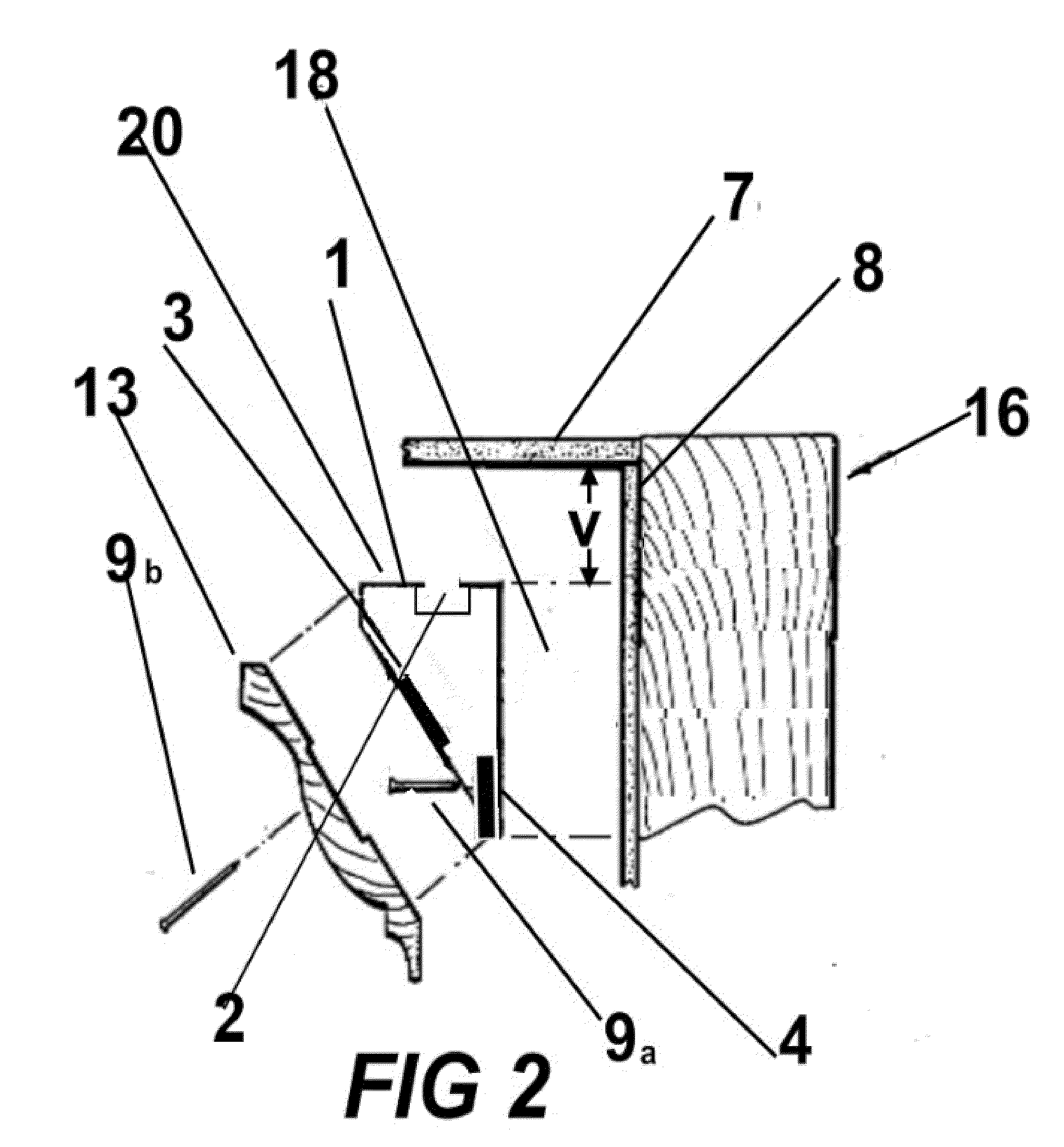
[0008]In another embodiment of the invention a decorative molding trimming system for installing a molded trim about the periphery of a room includes: a mounting block adapted to be secured to a wall of a room and extending about a border thereof, said mounting block having a first rigid member that provides a first contacting surface parallel to the wall and having a second rigid member that provides a second contacting surface oriented at an angle to a mounting surface of the molded trim, for aiding in securing the molded trim to the mounting block and to the wall.

Problems solved by technology

The application of molding is usually time consuming and often requires a skilled carpenter to avoid visually unpleasing effects of poor installation.
Skilled labor is often required to install crown molding properly.
As such, these installations tend to be expensive.
However, these are too cumbersome to be applied by the average home owner or do-it-your-selfer.
The problems related to the conventional installation of crown molding as indicated above are therefore compounded when installing crown molding in areas where direct lighting is required.

Method used


Image

  • Decorative molding trimming system and method of installing
  • Decorative molding trimming system and method of installing
  • Decorative molding trimming system and method of installing

Examples


Embodiment Construction

[0023]The following detailed description includes the best mode of carrying out the invention and is made for the purpose of illustrating the general principles of the invention and should not be taken in a limiting sense. The scope of the invention is determined by reference to the claims. Each part or function is assigned, even if structurally identical to another part, a unique reference number wherever that part is shown in the drawing figures.

[0024]The invention disclosed herein relates to a method and a system that allows for decorative molding trimming installation that is reliable, firm, accurate, simple, quick, inexpensive, and easy, not only for the skilled craftsman but for the “do-it-your-selfer”, for conventional installations and for installations requiring indirect lighting. Normally mechanical fasteners (such as nails or screws) cannot be used to attach light and soft material such as EPS to a wall. Also, nails and screws can not be used to attach other material (suc...


PUM

PropertyMeasurementUnit
Angleaaaaaaaaaa

Abstract

This invention generally relates to a method and system for installing decorative moldings including a mounting block made of a soft and light material adapted to be secured to a wall and extended about a border thereof, said mounting block having a first contacting surface parallel to the wall and a second contacting surface oriented at an angle to a mounting surface of a crown molding, said first contacting surface having a parallel rigid member thereon for securing the mounting block to the wall and the second contacting surface having an angular oriented rigid member thereon for securing the decorative molding to the mounting block.

Description

CROSS-REFERENCE TO RELATED APPLICATIONS[0001]This application claims the priority benefit under 35 U.S.C. 119 (e) of U.S. Provisional Application No. 61 / 185,620, Trim Molding and Method of Installing, filed on Jun. 10, 2009,the entire disclosure of which is hereby incorporated by reference herein.FIELD OF THE INVENTION[0002]This invention generally relates to methods and systems in the field of ornamental decorative moldings such as crown moldings, and relates more particularly to elongated or molded / cast decorative molding strips having outer surfaces with decorative ornamentation and surfaces for engaging supporting walls usually the ceiling and a vertical wall of a room space, through an intermediary component.BACKGROUND OF THE INVENTION[0003]Crown moldings cover and decorate the corner where room walls and ceilings meet. High speed wood molding machinery, modern extrusion techniques and casting technologies and materials have made it possible to produce large quantities of highl...

Claims


Application Information

Patent Timeline
IPC IPC(8): E04F13/073E04B1/38E04C2/20F21V19/00
CPCE04F19/0436F21S8/037F21V21/02F21S4/20F21Y2115/10
Inventor PAIDAR, REZAPAYDAR, DAVOOD
Owner PAIDAR REZA
Why Eureka
Eureka Blog
Learn More