Solar heat collection element with glass-ceramic central tube

a technology of solar heat collection and central tube, which is applied in the safety of solar heat collectors, solar heat collector details, light and heating apparatus, etc., can solve the problems of excessively high complexity of bellows mechanism, corrosion, and heat loss through the bellows mechanism, and achieves the effect of reducing operating temperature limits and reducing stress

Inactive Publication Date: 2010-12-16
CORNING INC
View PDF44 Cites 48 Cited by
  • Summary
  • Abstract
  • Description
  • Claims
  • Application Information

AI Technical Summary

Problems solved by technology

There are a number of problems with the conventional HCE design, including: the relatively high complexity (and associated parts and assembly cost) of the bellows mechanism, heat loss through the bellows mechanism (which may be as high as 10%), the aforementioned thermal expansion mismatches and associated temperature instabilities, the hydrogen permeability problems discussed above, corrosion problems when molten salt HTFs are employed, complex and costly coating techniques, relatively high weight, etc.

Method used


Image

  • Solar heat collection element with glass-ceramic central tube
  • Solar heat collection element with glass-ceramic central tube
  • Solar heat collection element with glass-ceramic central tube

Examples


Embodiment Construction

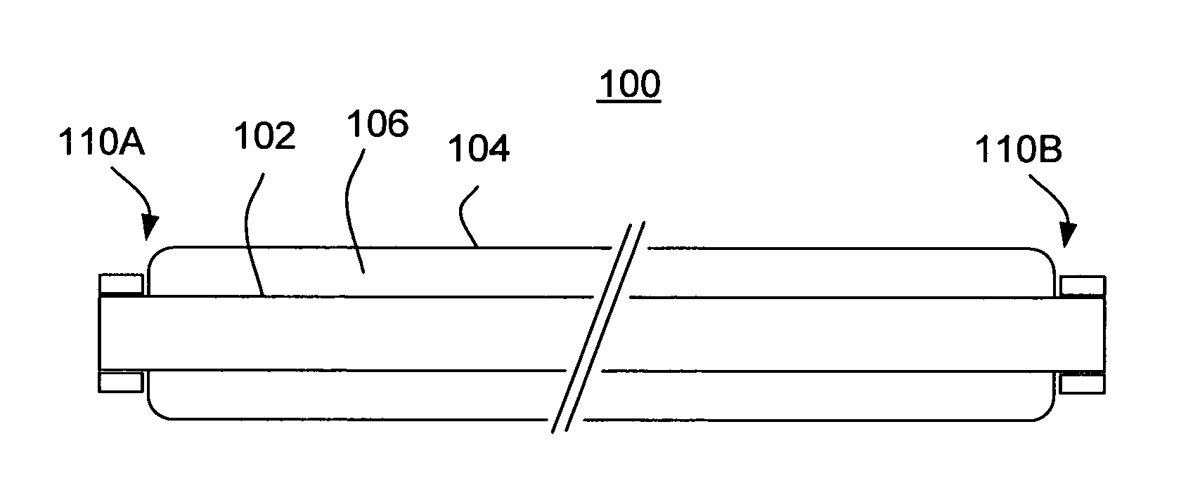
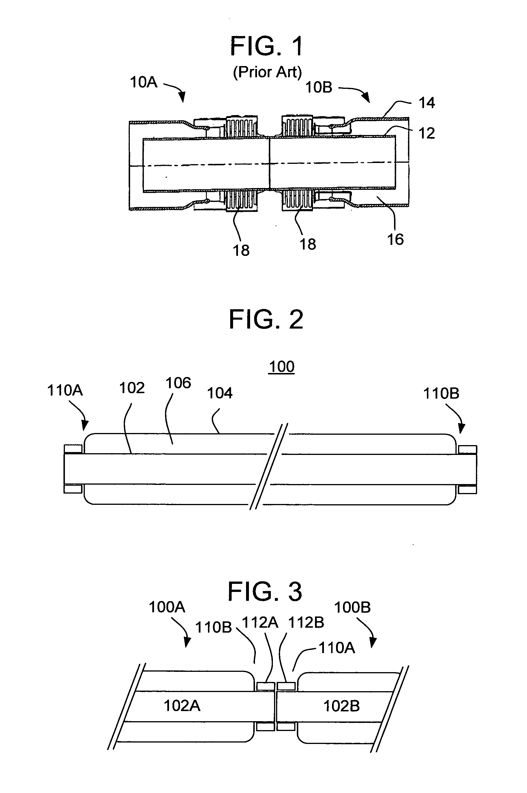
[0031]With reference to the drawings, wherein like numerals indicate like elements, there is shown in FIG. 2 a solar heat collection element (HCE) 100, which includes a central tube 102 formed from glass-ceramic material, and an outer tube 104 formed from glass material. The outer tube 104 is disposed coaxially with respect to the central tube 102 to form a volume 106 therebetween. The configuration of the central tube 102 and the outer tube 104 are preferably cylindrical, thereby yielding a cylindrical shaped space 106 (with a ring-shaped cross section).

[0032]Among the differences between the HCE 100 of the present invention and the HCEs of the prior art is the use of the central tube 102 formed from glass-ceramic material, as opposed to stainless steel. The outer tube 104 may be formed from a suitable glass, such as a borosilicate glass available from Corning Incorporated. Advantages of such a structure include: lower parts count and simplified assembly; greatly reduced hydrogen p...


PUM

PropertyMeasurementUnit
wavelengthsaaaaaaaaaa
thicknessaaaaaaaaaa
thicknessaaaaaaaaaa

Abstract

A solar heat collection element includes: a central tube (102) formed from glass-ceramic material; and an outer tube (104) formed from glass material disposed coaxially with respect to the central tube (102) to form a volume therebetween (106).

Description

CROSS-REFERENCE TO RELATED APPLICATIONS[0001]This application claims the benefit of priority to U.S. application No. 61 / 066,375, filed on Feb. 20, 2008, which is incorporated by reference herein.BACKGROUND OF THE INVENTION[0002]The present invention relates to a solar heat collection element (HCE), which is a tubular radiation absorbing device for solar thermal applications.[0003]HCEs may be employed in, among other applications, a parabolic trough-collector for a solar power plant. With reference to FIG. 1, the conventional heat collection structure comprises a plurality of HCEs 10, a pair 10A, 10B of which are shown coupled together. Each HCE 10 includes a central tube 12 and a glass tubular jacket (outer tube) 14 surrounding the central tube 12 so as to form a cylindrical space (with a ring-shaped cross section) 16 therebetween. Solar radiation is concentrated via a parabolic tracking mirror (not shown) and focused on the HCE 10 and converted into heat. The conventional HCE 10 is...

Claims


Application Information

Patent Timeline
Patent Type & Authority Applications(United States)
IPC IPC(8): F24J2/24F24J2/10F24S10/40F24S10/70F24S23/70
CPCF24J2/055F24J2/4636Y02E10/44F24J2/48F24J2/4652F24S10/45F24S40/80F24S70/10F24S70/30
Inventor BELLMAN, ROBERT ALANBOUTON, WILLIAM JOSEPHHALL, DOUGLAS WARRENMATTHEWS, KAREN IRENEUKRAINCZYK, LJERKA
Owner CORNING INC
Why Eureka
Try Eureka