Multi-sectional co-cured golf shaft

Active Publication Date: 2010-12-16
WILSON SPORTING GOODS
View PDF5 Cites 18 Cited by
  • Summary
  • Abstract
  • Description
  • Claims
  • Application Information

AI Technical Summary

Benefits of technology

[0053]The shaft 12 of the present invention provides numerous advantages over existing golf shafts. The shaft 12 provides exceptional control and accuracy and enables the golfer to swing his or her golf club faster thereby generating greater clubhead speed and ball speed. The shaft 12 provides these benefits while being significantly lighter than conventional steel golf shafts. The shaft 12 is also configured for use in competitive play including tournament play by satisfying the requirements of The Rules of Golf as approved by the U.S. Golf Association and the Royal and Ancient Golf Club of St. Andrews, Scotland effective Jan. 1, 2008 (“The Rules of Golf”). Accordingly, the term “shaft is configured for organized, competitive play” refers to a shaft that fully meets the golf shaft rules and / or requirements of The Rules of Golf.

Problems solved by technology

However, steel golf shafts also have some drawbacks.
This additional weight can have an undesirable affect on the swing speed of some golfers.
Other golfers can find steel shafts to be too heavy, especially when used over the course of an entire round of play.
Steel golf shafts can also be too stiff for some golfers.
While other golfers can find steel shafts too uncomfortable because too much vibrational energy is transmitted from the club head to the golfer's hands during use.
However, like steel shafts, graphite golf shafts also have drawbacks.
Graphite golf shafts are generally less stable, and provide less torsional stability, than steel shafts.
Accordingly, a typical graphite shaft offers less control and accuracy than a steel shaft.
Some golfers find graphite shafts to be too light or too flexible.
Graphite shafts can be less durable and, in some instances, can provide inconsistent performance.

Method used


Image

  • Multi-sectional co-cured golf shaft
  • Multi-sectional co-cured golf shaft
  • Multi-sectional co-cured golf shaft

Examples


Embodiment Construction

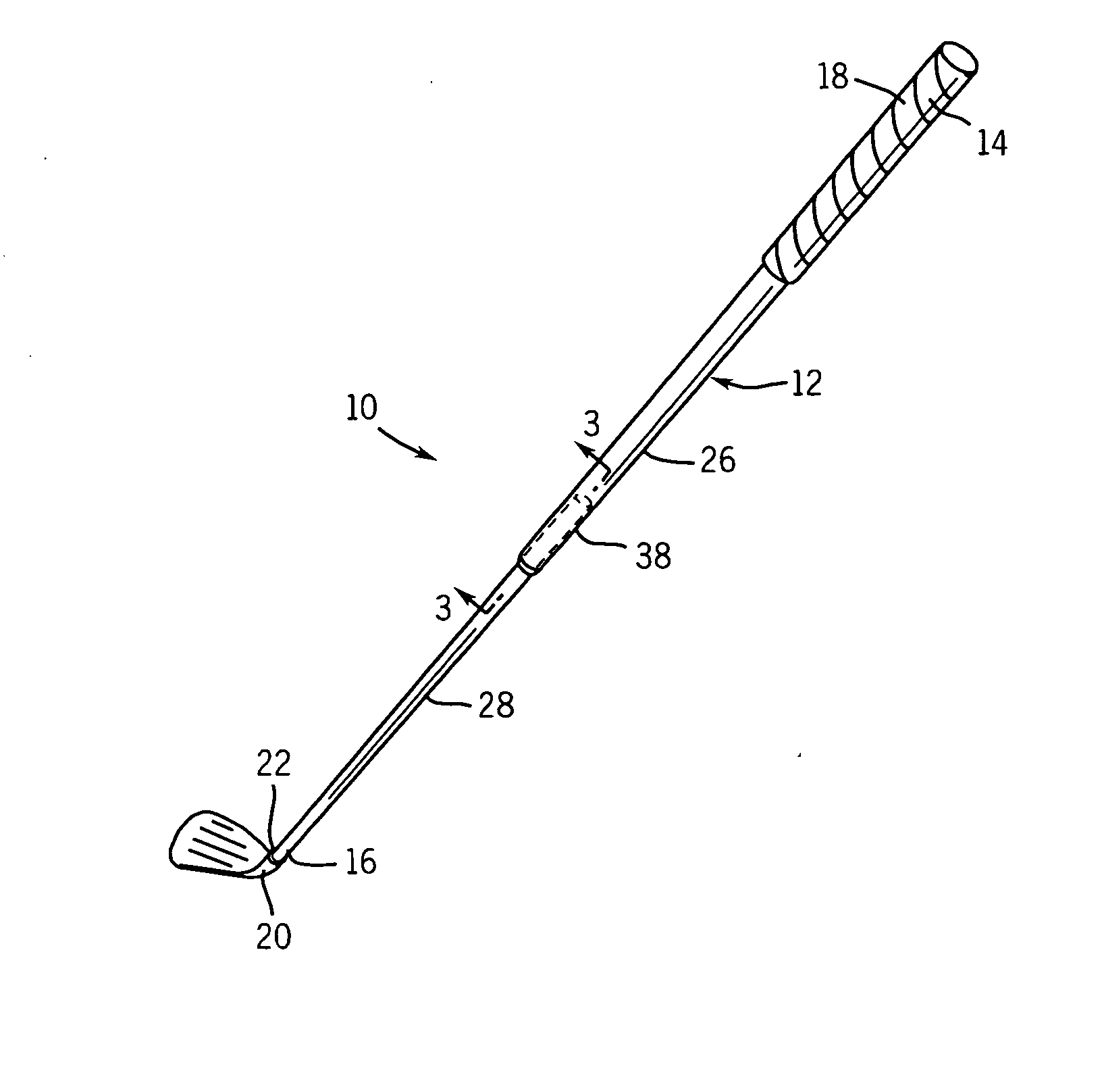
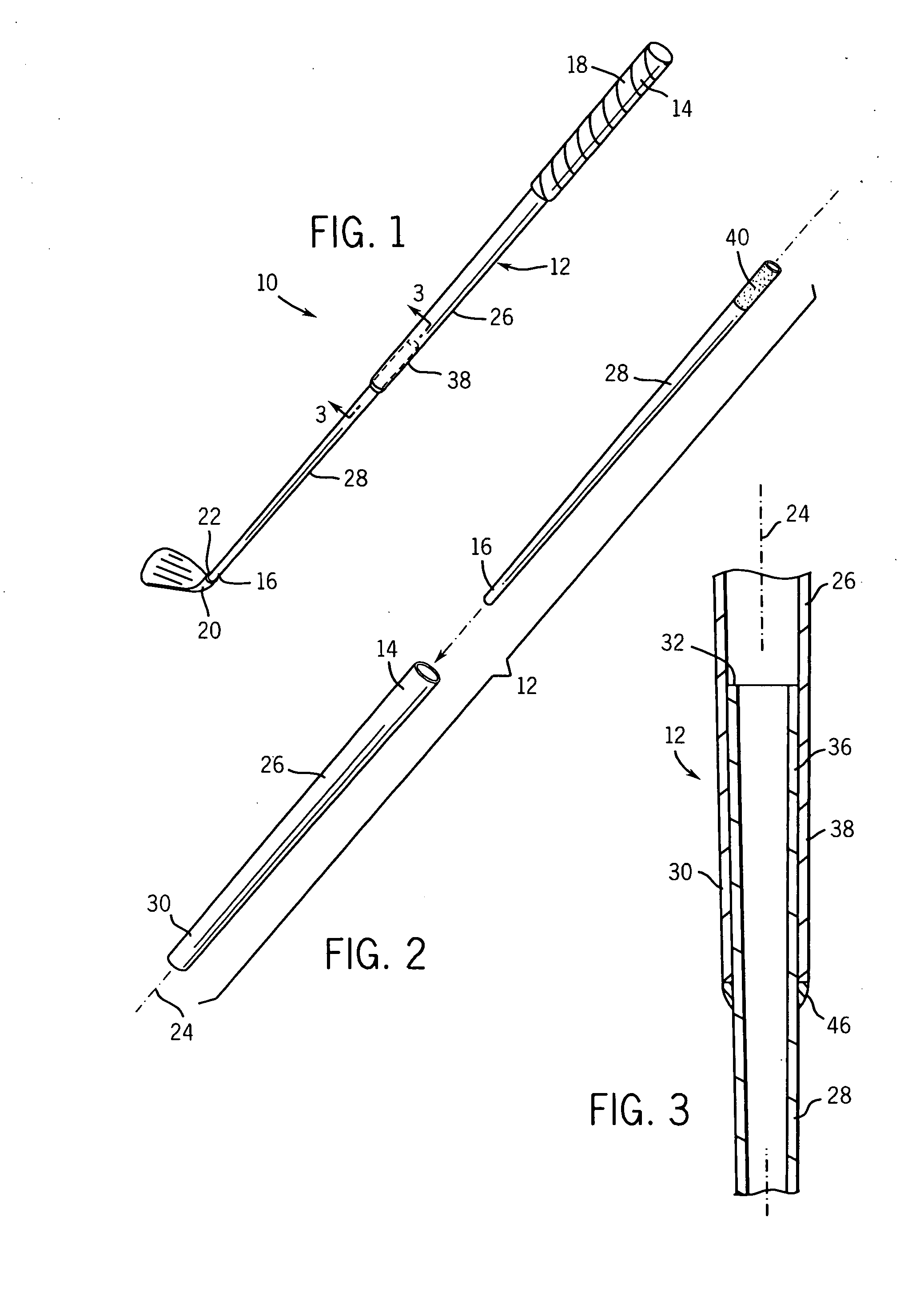
[0021]Referring to FIG. 1, a golf club is indicated generally at 10. The golf club 10 of FIG. 1 is configured as a #6 iron type club of a set. The present invention can also be formed as, and is directly applicable to, #2 through #9 iron clubs, fairway woods, drivers, hybrids, wedges and combinations thereof in sets of golf clubs. The golf club 10 is an elongate implement configured for striking a golf ball and includes a golf shaft 12 having a butt end 14 and a tip end 16, a grip 18 coupled to the butt end 14, and a club head 20 coupled to the tip end 16.

[0022]The grip 18 is a conventional handle structure of generally hollow construction. The grip 18 has an open end configured for slidably receiving the butt end 14 of the shaft 12. The grip 18 is formed of a generally soft resilient material, such as, for example, rubber, polyurethane, leather, a thermoplastic, an elastomer, or combinations thereof. Alternatively, the grip 18 can be formed of two or more layers of material. In yet...


PUM


Abstract

A shaft for a golf club having a total length and a total weight. The shaft includes first and second tubular portions. The first and second tubular portions are formed of first and second materials, respectively. The second tubular portion has a proximal end and a tip end. The tip end has an outside diameter of less than 0.400 inches. The distal end of the first tubular portion is co-cured to the proximal end of the second tubular portion. The shaft has a resistance to twisting about a longitudinal axis of the shaft, when tested under a torsional stability test and measured at an approximate midpoint of the total length of the shaft, of less than 2.0 degrees in a torsional stability test. The shaft when measured from the tip end of the shaft in a balance point test device has a balance point of less than 46 percent.

Description

FIELD OF THE INVENTION[0001]The present invention relates generally to a shaft for a golf club. In particular, the present invention relates to a golf shaft including a tip portion and a butt end portion formed of different materials.BACKGROUND OF THE INVENTION[0002]Shafts for golf clubs are well known. Golf shafts are typically specified in terms of flexibility, e.g., stiff flex versus regular flex, and are typically formed from one of two different material categories: steel or graphite. Golf shafts made of steel generally have higher torsional stability than graphite shafts and can transmit vibrational energy more directly from the club head to the user's hands during use. The higher torsional stability and stiffness of steel shafts offers golfers greater control and accuracy and provide golfers with a greater sense of the location of the clubhead during his or her swing. Additionally, the transmission of vibrational energy from the clubhead to the hands of the user is desirable ...

Claims


Application Information

Patent Timeline
IPC IPC(8): A63B53/10
CPCA63B53/10A63B53/12A63B2209/00A63B59/0074A63B59/0092A63B59/0014A63B60/10A63B60/06A63B60/54A63B60/08A63B60/42A63B60/0085
Inventor HULOCK, RICHARD P.PERGANDE, JON C.THURMAN, ROBERT T.
Owner WILSON SPORTING GOODS
Why Eureka
Try Eureka