Platen roller assemblies for printer and methods of removal therefrom

a technology of platen roller and printer, which is applied in the direction of bearings, shafts and bearings, printing, etc., can solve the problems of platen roller, high wear and tear, and difficulty in accessing some of these components, and achieves the effect of reducing the number of parts

Active Publication Date: 2010-12-23
HAND HELD PRODS
View PDF7 Cites 39 Cited by
  • Summary
  • Abstract
  • Description
  • Claims
  • Application Information

AI Technical Summary

Benefits of technology

[0006]Accordingly, the present disclosure is directed to a printer including a platen roller assembly. The platen roller assembly includes a platen roller, a retaining clip, a plurality of bearings, and a pulley assembly. The platen roller defines a longitudinal axis. The platen roller may be selectively coupled and uncoupled to/from the support body independent of the pulley assembly. The retaining clip mounts to a support body of the pr

Problems solved by technology

In the course of normal wear and tear, many of these components begin to fail or lose efficiency.
In particular, some of these components, e.g., a platen roller, are susceptible to high

Method used


Image

  • Platen roller assemblies for printer and methods of removal therefrom
  • Platen roller assemblies for printer and methods of removal therefrom
  • Platen roller assemblies for printer and methods of removal therefrom

Examples


Embodiment Construction

[0035]Particular embodiments of the present disclosure will be described herein with reference to the accompanying drawings. As shown in the drawings and as described throughout the following description, and as is traditional when referring to relative positioning on an object, the term “proximal” refers to the end of the apparatus that is closer to the user and the term “distal” refers to the end of the apparatus that is farther from the user. In the following description, well-known functions or constructions are not described in detail to avoid obscuring the present disclosure in unnecessary detail.

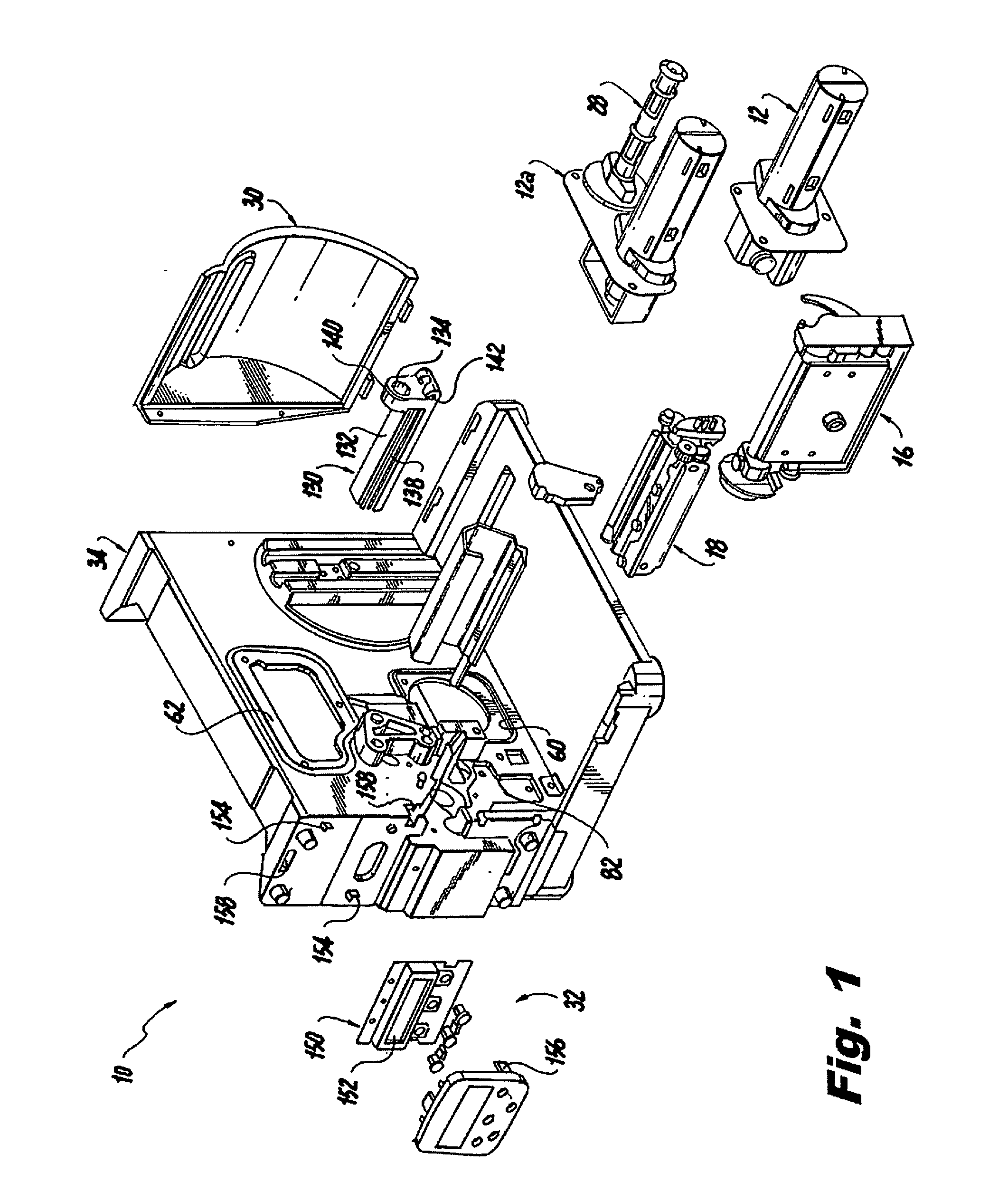
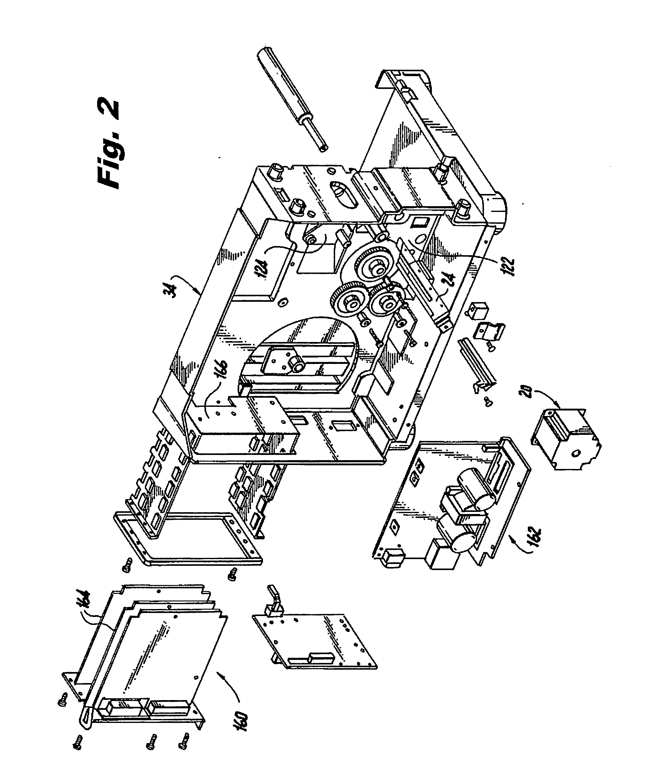
[0036]FIGS. 1 and 2 illustrate perspective views of a printer, with parts separated, shown generally as 10. More specifically, FIG. 1 illustrates the printing components of the printer and FIG. 2 illustrates the electrical and drive components of the printer. An example of such a printer is disclosed in U.S. patent Ser. No. 11 / 491,798, filed Jul. 24, 2006, now U.S. Pat. No. 7,600,684,...


PUM


Abstract

A platen roller assembly for a printer includes a platen roller, a retaining clip, a plurality of bearings, and a pulley assembly. The platen roller defines a longitudinal axis. The retaining clip mounts to a support body of the printer and is positioned to retain the platen roller relative to the support body. The plurality of bearings are operably coupled to the platen roller. Each of the bearings permit rotational movement of the platen roller about the longitudinal axis thereof. The pulley assembly is mounted to the support body and is operably associated with one or more of the bearings. The pulley assembly includes a pulley and a belt. The belt is operably coupled to the pulley such that the platen roller rotates in response to rotational movement of the belt. The platen roller may be selectively coupled and uncoupled to/from the support body independent of the pulley assembly.

Description

CROSS-REFERENCE TO RELATED APPLICATIONS[0001]The present application claims the benefit of and priority to U.S. Provisional Patent Application Ser. No. 61 / 187,892, filed Jun. 17, 2009, the entire contents of which are incorporated herein by this reference.BACKGROUND[0002]1. Technical Field[0003]The present disclosure relates to printers in general and, more particularly, to platen roller assemblies for use with printers.[0004]2. Description of Related Art[0005]Printers have many components operating together to provide an effective drive system which often includes a belt drive. These components may include rollers, pulleys, belts, gears, bearings, etc. In the course of normal wear and tear, many of these components begin to fail or lose efficiency. In particular, some of these components, e.g., a platen roller, are susceptible to high wear and tear and must be readjusted, repaired, or even replaced quite often. Accessing some of these components can be quite cumbersome and time con...

Claims


Application Information

Patent Timeline
IPC IPC(8): B41F27/12F16C13/00
CPCB41J2/325B41F27/00B41J11/04
Inventor COLQUITT, STEVENCHRISTENSEN, CHRIS
Owner HAND HELD PRODS
Why Eureka
Try Eureka