Disposable pump, a dispensing system comprising a pump and a method for dispensing liquid

a technology of a dispensing system and a pump, which is applied in the direction of liquid/fluent solid measurement, container, and opening closed containers, etc., can solve the problems of inability to automatically return the piston, the pump's function is severely impaired, and the feeding of liquid from the pump is relatively complicated, etc., to achieve the effect of robust pump, convenient handling and greater suction for

Active Publication Date: 2010-12-23
ESSITY HYGIENE & HEALTH AB
View PDF21 Cites 26 Cited by
  • Summary
  • Abstract
  • Description
  • Claims
  • Application Information

AI Technical Summary

Benefits of technology

[0091]It has not previously been realised, that plastic material resiliency could be sufficient to overcome the negative pressure created in a collapsible container during emptying thereof.
[0092]Advantageously, the pump consists of a one-piece housing and a one-piece regulator, hence of only two parts. The use of few parts is advantageous in view of economics for manufacturing and assembling the parts, and contributes to the robustness of the pump.
[0093]The plastic materials in the pump need not be identical, but should preferably be of the same type, such that the pump may be recycled as a single unit. Moreover, the compressible bottle should preferably be of the plastic material type as the pump, such that the entire system may be recycled as a single unit. This is particularly advantageous since in this case the persons taking care of the emptied systems may avoid any mess caused by liquid rests from the container or the pump leaking out. As will be understood from the following description of detailed embodiments, the suggested system may be designed such that the pump maintains a sealed condition even when the bottled is emptied. Such embodiments will of course be particularly easy to handle after use.
[0094]Advantageously, the container is a semi-rigid collapsible container. By semi-rigid is meant a container as mentioned in the introduction, which has at least one relatively rigid portion, towards which the collapse of the other, less rigid portions will be directed. This type of collapsible containers is advantageous in that information may be printed on the rigid portion, the information being clearly visible and undistorted regardless of the state of collapse of the container. Moreover, for some contents, containers having at least one relatively rigid wall may be preferable over bags. However, collapsible containers having at least one relatively rigid wall may require a greater suction force generated from the pump in order to overcome the negative pressure created in the container during emptying thereof, than the bags. A particular advantage with the proposed system is that it may be made efficient to overcome the relatively large negative pressure generated also by semi-rigid collapsible containers.

Problems solved by technology

However, the pump of EP 1 215 167 would not be able to generate a suction pressure sufficient to empty a collapsible container, as the negative pressure from the collapsible container would inhibit the pressure bulb from expanding, and hence the function of the pump would be severely impaired if used with a collapsible container.
From the above description, it is understood that if a negative pressure (a negative pressure) is maintained inside the container, as would be the case using a collapsible container, the piston will not be able to automatically return, which means that the feeding of liquid from the pump is relatively complicated.
Hence, none of the above-mentioned pumps are satisfactory for use with a collapsible container.
Instead, known pumps that are used for collapsible containers are relatively expensive, including a relatively large number of components and often a great variety of materials.

Method used


Image

  • Disposable pump, a dispensing system comprising a pump and a method for dispensing liquid
  • Disposable pump, a dispensing system comprising a pump and a method for dispensing liquid
  • Disposable pump, a dispensing system comprising a pump and a method for dispensing liquid

Examples


Embodiment Construction

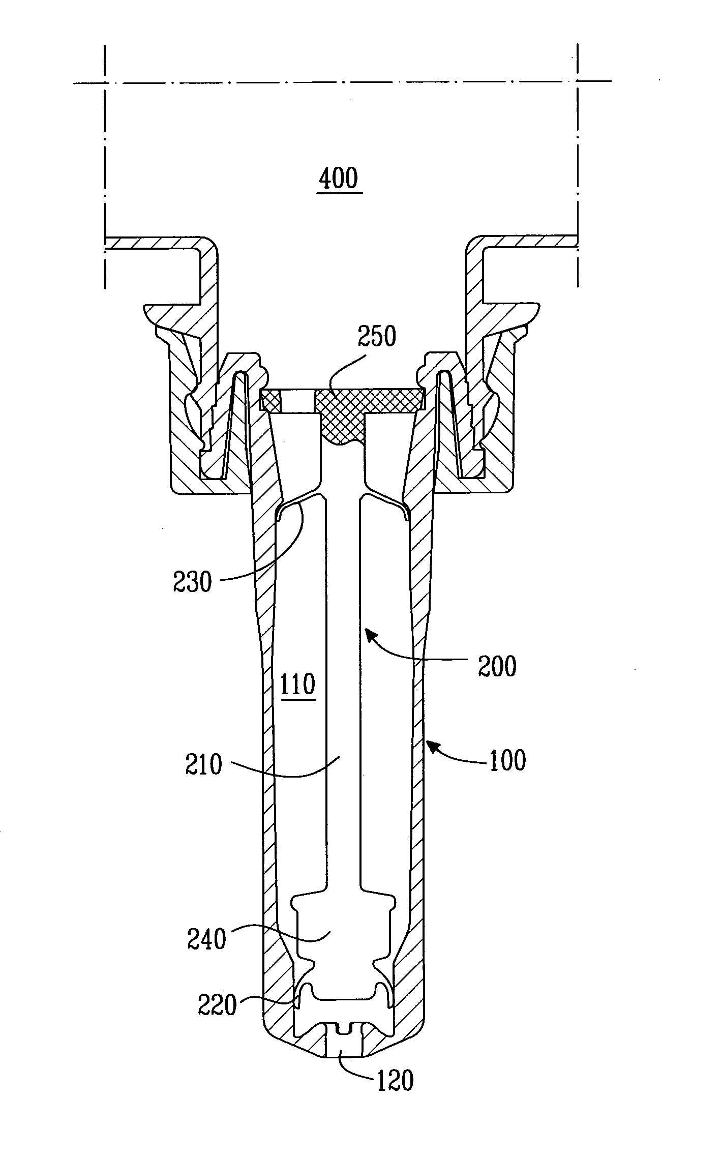
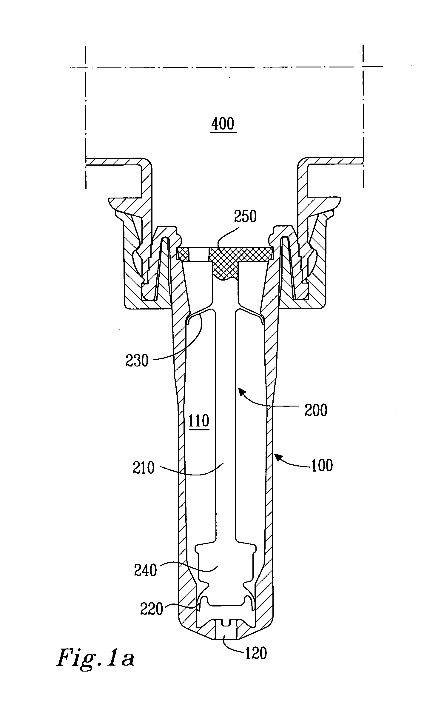
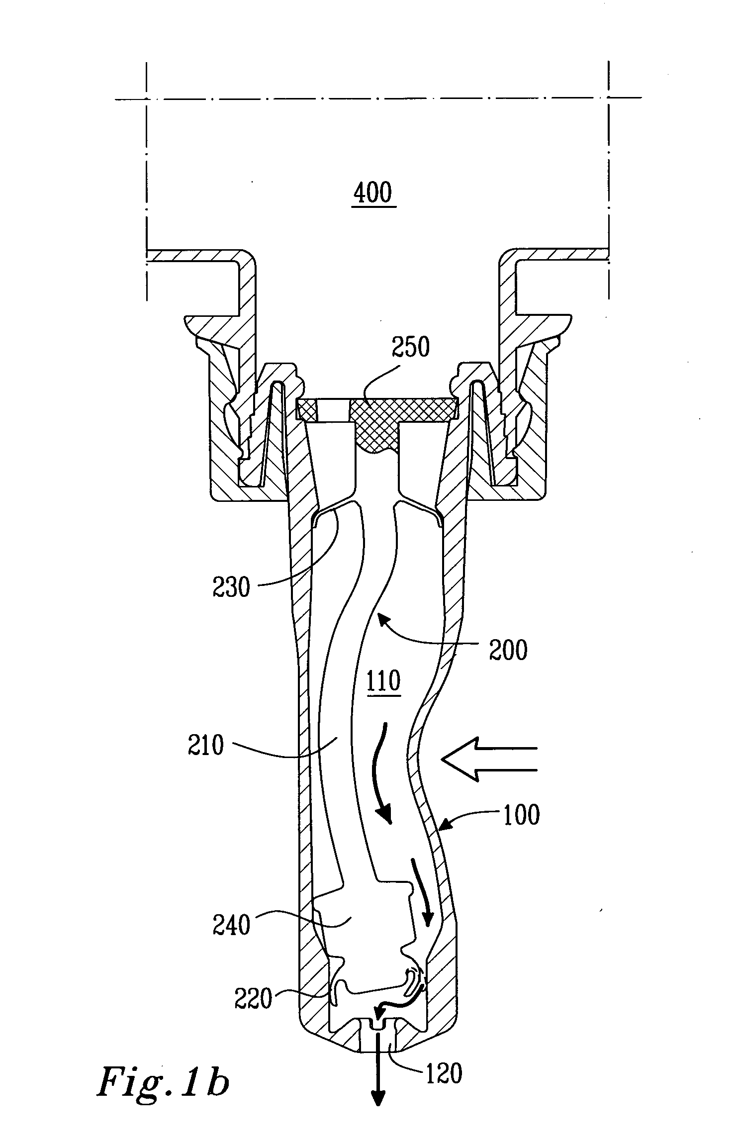
[0112]FIGS. 1a to 1d schematically illustrate one dispensing-refill cycle of an embodiment of a pump 1 in accordance with the invention. For simplicity, FIGS. 1a to 1d have been stripped from some of the features being dispensable when explaining the general functions of the pump. Instead, detailed features of the illustrated embodiment are explained in relation to the other figures and in connection with additional advantages of the invention.

[0113]When in use, the pump 1 is to be sealingly connected to a container containing liquid material such as liquid soap or alcohol detergent. The container is schematically denoted 400 in FIGS. 1a to 1d. The pump 1 comprises a housing 100 and a regulator 200 being fixedly arranged in the housing 100. The housing 100 forms a chamber 110 in which, as will be described later, the pressure may be varied for dispensing liquid from the pump 1 or refilling liquid from the compressible container 300. Moreover, the housing 100 forms a dispensing openi...


PUM


Abstract

A disposable pump for a liquid dispensing system including a compressible container, includes—a housing forming a chamber and a dispensing opening wherein the pressure in the chamber may be varied for pumping liquid from the container to the chamber, and from the chamber to the dispensing opening, and a regulator fixedly arranged in the chamber for regulating a flow of liquid between the container and the chamber and between the chamber and the dispensing opening, the regulator including an outer valve for regulating the flow between the chamber and the dispensing opening. The pump may assume a closed position, in which a volume of liquid is drawn from the container to the chamber by a negative pressure created in the chamber, and a dispensing position, in which a volume of liquid is drawn from the chamber to the dispensing opening. The outer valve is displaceable between a symmetrical position corresponding to the closed position, where the outer valve is in sealing contact with the housing, and a tilted position corresponding to the dispensing position, where the outer valve is movable to and from sealing contact with the housing dependent on the pressure in the chamber, and the displacement of the outer valve from the symmetrical position to the tilted position requiring external force being applied to the pump and transferred to the regulator independent of the pressure variations in the chamber.

Description

TECHNICAL FIELD[0001]The present invention relates to a disposable pump for a dispensing system for dispensing liquids, in particular for a dispensing system which comprises a compressible container.BACKGROUND OF THE INVENTION[0002]This invention relates to the field of disposable suction pumps for dispensing a liquid material, such as soap or alcohol detergent out of a container such as a bottle or the like. A vast number of different suction pumps have been proposed in the past. Generally, many suction pumps include a pressure chamber, from which a volume of liquid may be dispensed. The liquid leaving the chamber creates a negative pressure in the fluid chamber, which negative pressure functions to draw new liquid from the container into the pressure chamber, which thereby is filled and ready to dispense a new volume of liquid.[0003]In use, the container is interconnected to the pump, and introduced in a dispenser, which is typically fixedly arranged on a wall in a bathroom or the...

Claims


Application Information

Patent Timeline
Patent Type & Authority Applications(United States)
IPC IPC(8): B67D7/00B65D37/00
CPCA47K5/1209
Inventor NILSSON, HUGO
Owner ESSITY HYGIENE & HEALTH AB
Why Eureka
Try Eureka