
Plate spring for a voice coil motor

a voice coil motor and plate spring technology, applied in the direction of spring/damper, leaf spring, belleville-type springs, etc., can solve the problems of poor anti-torsion strength, easy damage to the suspension arms, poor anti-torsion strength, etc., and achieve the effect of improving the anti-torsion strength

Inactive Publication Date: 2010-12-23
ASIA OPTICAL INT LTD
View PDF8 Cites 27 Cited by
  • Summary
  • Abstract
  • Description
  • Claims
  • Application Information

AI Technical Summary

Benefits of technology

[0007]Therefore, the object of the present invention is to provide a plate spring for a voice coil motor, which has enhanced anti-torsion strength.

Problems solved by technology

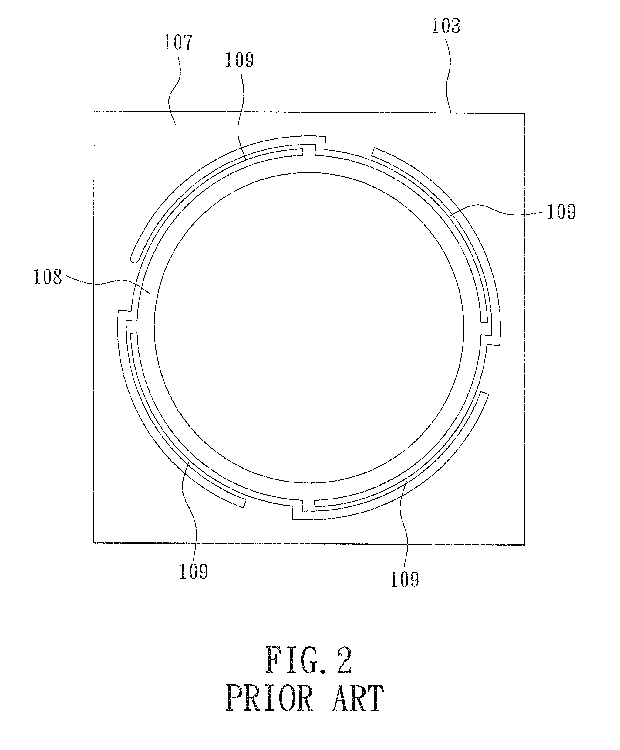
However, a width and a thickness of each suspending arm 109 of the plate springs 103 are merely 0.1 mm and 0.05 mm, respectively, meaning that anti-torsion strength is poor, and the suspending arms 109 are easily damaged during a process of assembling the lens 2.
However, the anti-torsion strength of the plate spring 3 is still not good.
Therefore, how to design a plate spring, which possesses good anti-torsion strength without changing axial elasticity, is an important issue in the industry.

Method used


Image

  • Plate spring for a voice coil motor
  • Plate spring for a voice coil motor
  • Plate spring for a voice coil motor

Examples


Embodiment Construction

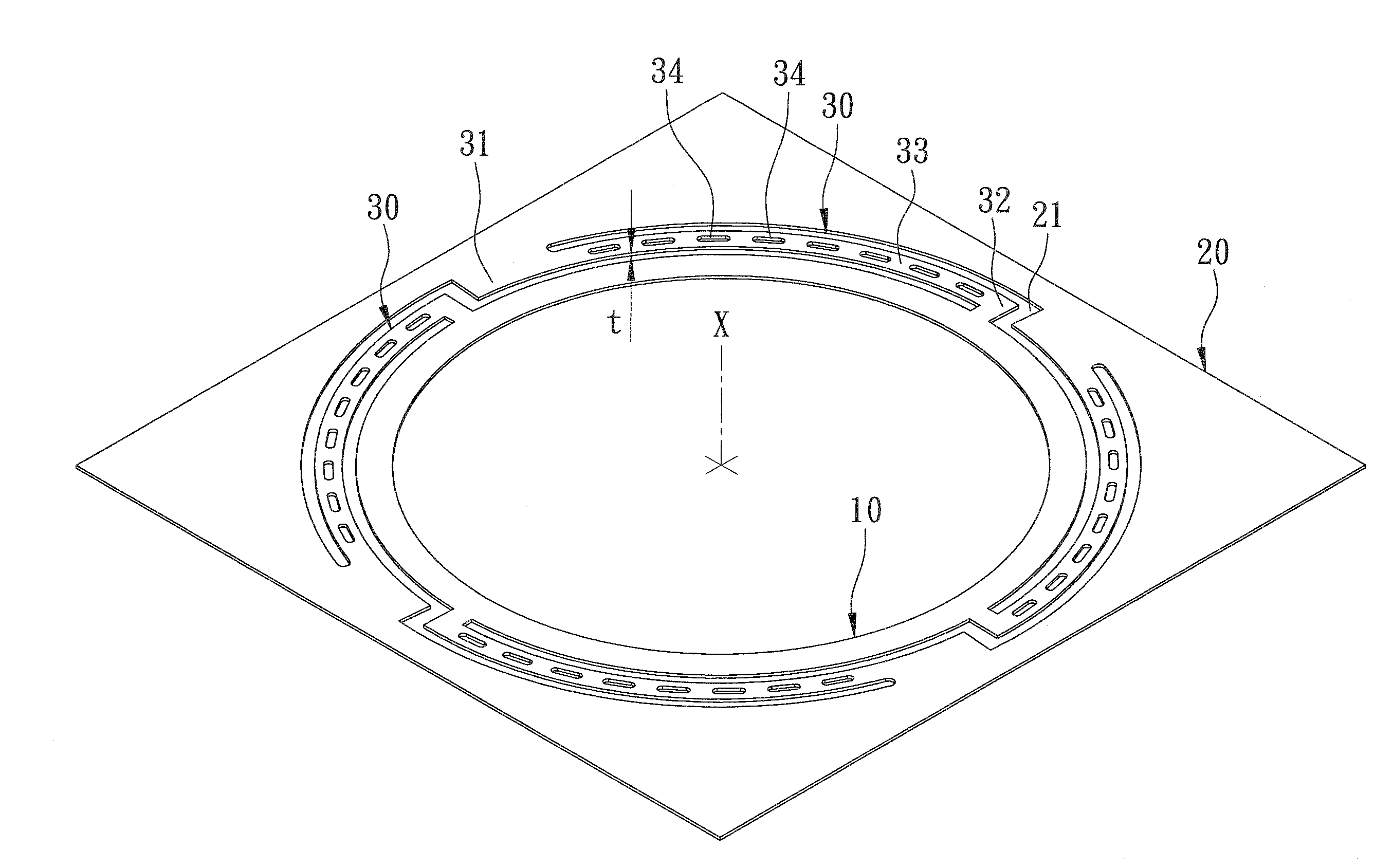
[0016]Referring to FIGS. 4 and 5, a preferred embodiment of a plate spring for a voice coil motor according to the present invention is shown to comprise an internal surrounding portion 10, an external surrounding portion 20, and a plurality of suspending arms 30.

[0017]The internal surrounding portion 10 is in a form of a ring that surrounds an axis (X). The external surrounding portion 20 surrounds the internal surrounding portion 10, is spaced apart from the internal surrounding portion 10, and has a plurality of cutouts 21. The suspending arms 30 interconnect the internal surrounding portion 10 and the external surrounding portion 20, and extend into the cutouts 21, respectively.

[0018]Each of the suspending arms 30 includes a first connecting segment 31 that is connected to the external surrounding portion 20 and that extends radially inward, a second connecting segment 32 that is connected to the internal surrounding portion 10 and that extends radially outward, and a working se...


PUM


Abstract

A plate spring includes an internal surrounding portion, an external surrounding portion, and a plurality of suspending arms. The external surrounding portion surrounds the internal surrounding portion and is spaced apart from the internal surrounding portion. The suspending arms interconnect the internal surrounding portion and the external surrounding portion. Each of the suspending arms includes a first connecting segment, a second connecting segment, and a working segment. The first connecting segment is connected to the external surrounding portion and extends inwardly. The second connecting segment is connected to the internal surrounding portion and extends outwardly. The working segment interconnects the first and second connecting segments and is formed with a plurality of hole portions which are spaced apart from each other.

Description

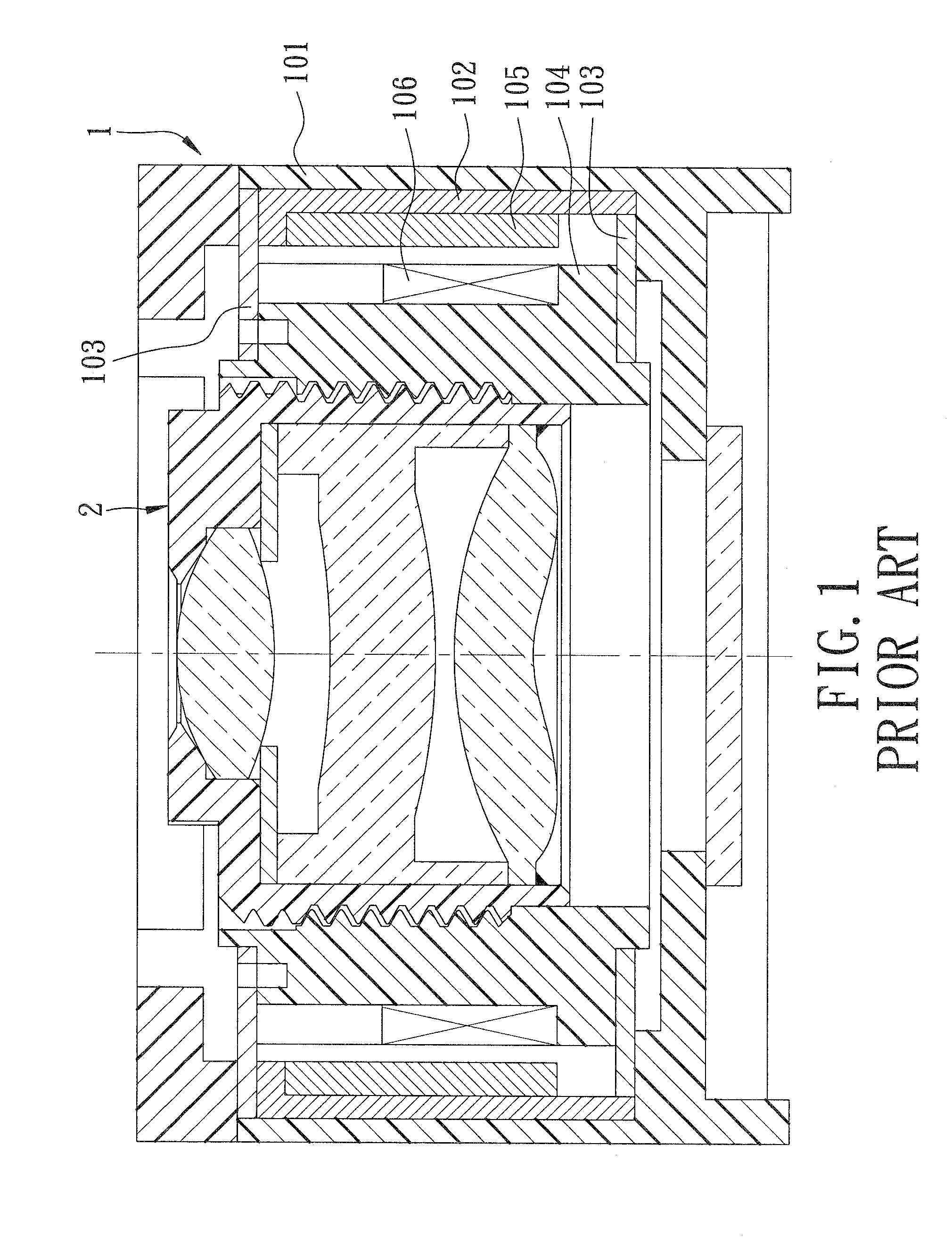
CROSS-REFERENCE TO RELATED APPLICATION[0001]This application claims priority of Taiwanese Application No. 098121006, filed on Jun. 23, 2009.BACKGROUND OF THE INVENTION[0002]1. Field of the Invention[0003]The present invention relates to a component of an optical variable focus lens, more particularly to a plate spring for a voice coil motor.[0004]2. Description of the Related Art[0005]Referring to FIG. 1, a conventional auto-focusing lens device includes a voice coil motor (VCM) 1 and a lens 2. The voice coil motor 1 has a case 101, a yoke 102 disposed in the case 101, upper and lower plate springs 103 disposed in the case 101, a carrier 104 connected to the plate springs 103, a magnet set 105 disposed on the yoke 102, and a coil 106 disposed on the carrier 104. The lens 2 is locked threadedly in the carrier 104. As shown in FIG. 2, each of the plate springs 103 has an external surrounding portion 107, an internal surrounding portion 108, and a plurality of suspending arms 109 exten...

Claims


Application Information

Patent Timeline
IPC IPC(8): F16F1/32
CPCF16F1/027
Inventor CHEN, YING-JUIHUANG, YU-CHUN
Owner ASIA OPTICAL INT LTD
Learn More