Rotary damper

a technology of rotors and dampers, applied in the field of rotor dampers, can solve the problems of high manufacturing cost, and achieve the effects of increasing resistance, flexural modulus, and greatly improving the torsional strength of the rotor member

Inactive Publication Date: 2005-01-11
NIFCO INC
View PDF8 Cites 16 Cited by
  • Summary
  • Abstract
  • Description
  • Claims
  • Application Information

AI Technical Summary

Benefits of technology

In order to attain the above objects, a rotary damper of the invention includes a cylindrical member having walls along a radial line on an inner peripheral surface of a cylindrical chamber; and a rotor member having vanes moving along the inner peripheral surface of the cylindrical chamber, so that a resistance is applied to a relative rotation between the cylindrical member and the rotor member by applying resistance of a viscous fluid filled in the cylindrical chamber to the vanes. In the rotary damper of the invention, the rotor member is formed of a thermoplastic resin containing inorganic filler or fiber. Since a flexural modulus is increased, the torsional strength of the rotor member is greatly improved.
A diameter of the cylindrical chamber may be different in two stages, so that the inner peripheral surface of a smaller diametrical portion substantially contacts an outer edge of the vane in the diametrical direction, and the inner peripheral surface of a larger diametrical portion faces the outer edge of the vane in the diametrical direction with a suitable space therebetween, thereby further increasing the resistance when the vane passes through the inner peripheral surface of the smaller diameter portion.

Problems solved by technology

In order to obtain the rigidity for this end, although a metal is a useful material for the rotor member, such a small part made of the metal results in a high manufacturing cost.

Method used


Image

  • Rotary damper
  • Rotary damper
  • Rotary damper

Examples


Embodiment Construction

Hereunder, embodiments of the present invention will be described in detail with reference to the accompanying drawings.

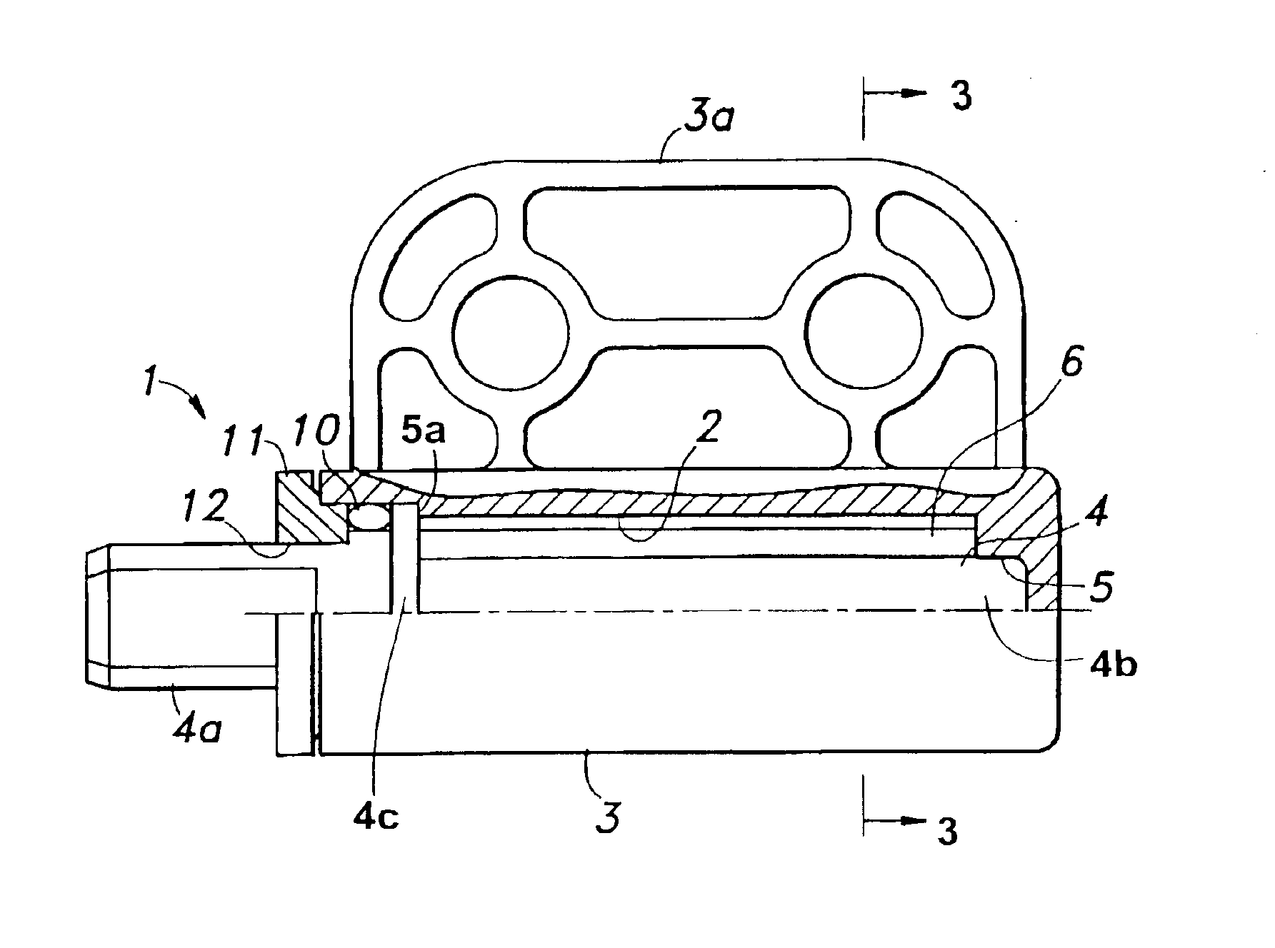
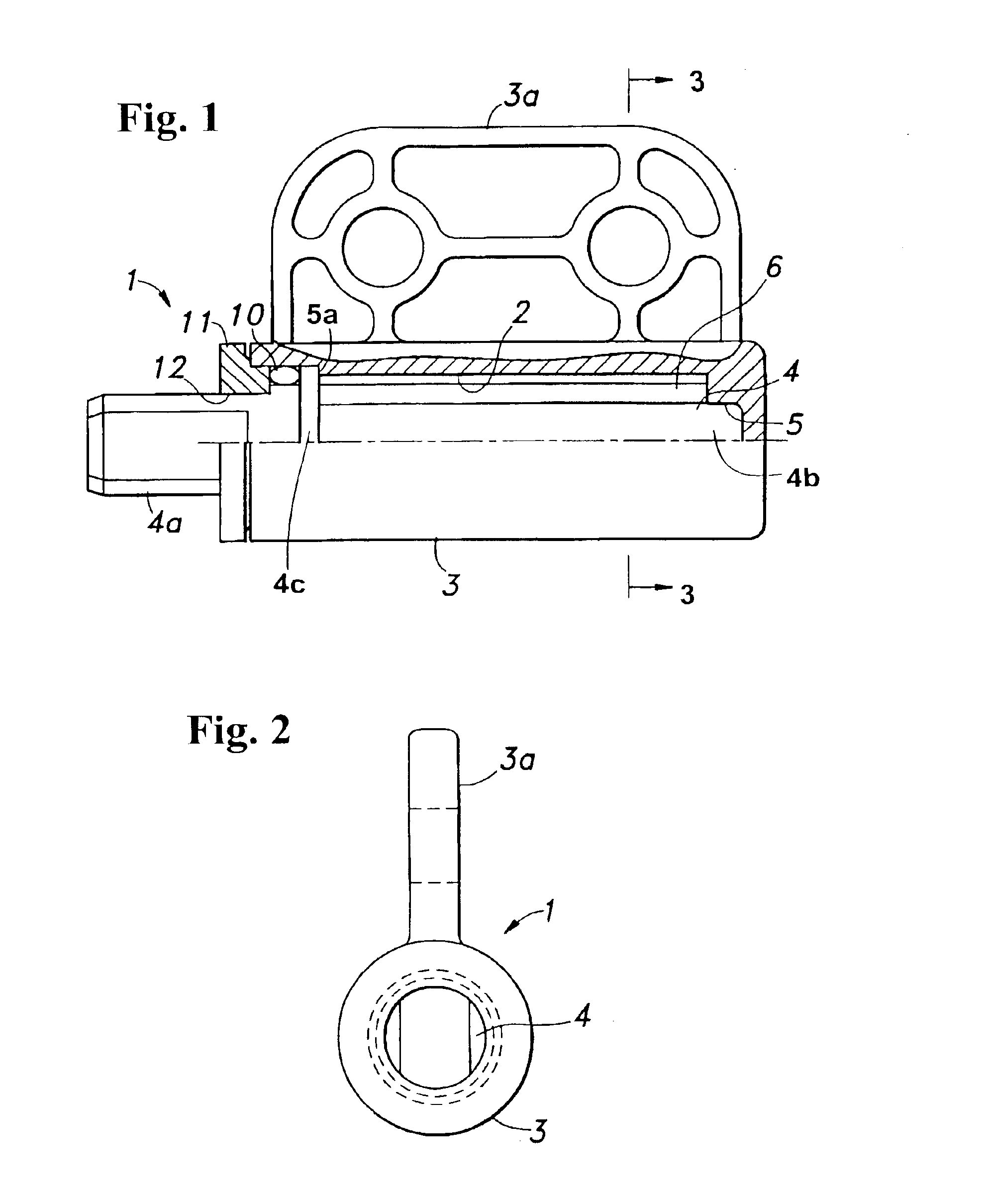
FIGS. 1 and 2 show a rotary damper to which the present invention is applied. A rotary damper 1 includes a cylindrical member 3 having a cylindrical chamber 2 formed therein; and a rotor member 4 rotatably housed in the cylindrical chamber 2 and having one shaft end projecting from the cylindrical member 3. The rotary damper 1 is disposed to, for example, a hinge shaft of a service lid provided at a printer to freely open. In that case, a stay-portion 3a projecting from an outer peripheral surface of the cylindrical member 3 is fixed on a side of a main body of the printer, and one shaft end 4a of the rotor member 4 is fixed on the lid side.

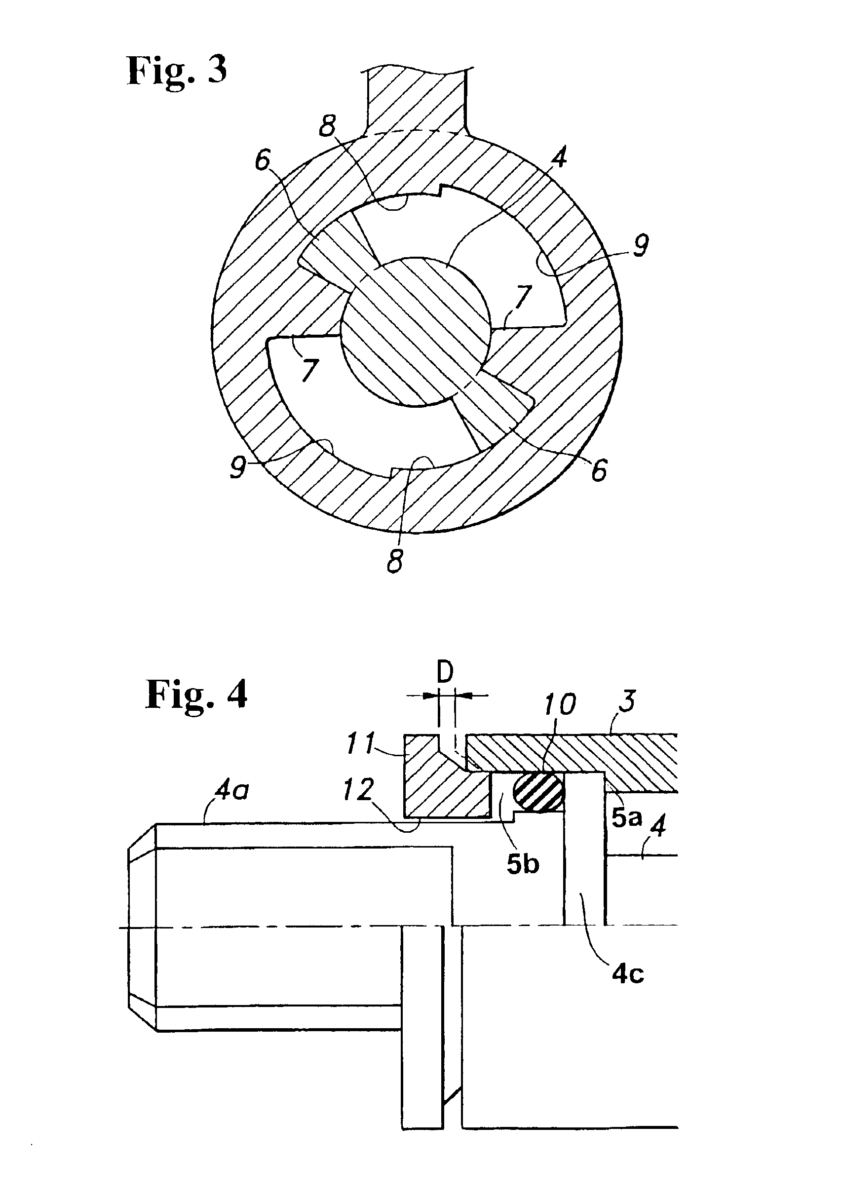
The other shaft end 4b of the rotor member 4 is inserted into a central hole or depression 5 formed on a bottom wall of the cylindrical chamber 2. A pair of vanes 6 is formed on an outer peripheral surface of the rotor member 4,...


PUM


Abstract

A rotary damper includes a cylindrical member having walls on an inner peripheral surface of a cylindrical chamber along a radial line, and a rotor member having vanes moving along the inner peripheral surface of the cylindrical chamber. A resistance force of a viscous fluid filled in the cylindrical chamber is applied to the vanes when the cylindrical member rotates relative to the rotor member. The rotor member is formed of a thermoplastic resin containing inorganic filler or fiber. Thus, the rotor member having high strength can be obtained.

Description

BACKGROUND OF THE INVENTION AND RELATED ART STATEMENTThe invention relates to a rotary damper, more particularly, to a rotary damper for producing rotational resistance on a hinge shaft of an opening-closing member.A rotary damper is often used for applying the rotational resistance to a hinge shaft of an opening-closing member, such as a console box and grove box in a car, a display panel of a lap-top computer and a service lid of a printer, so that the opening-closing member is not suddenly closed or opened.As this kind of a rotary damper, a rotary damper using a viscous liquid is known. For example, Japanese Patent Publication (Tokkai) No. 64-30938 discloses a rotary damper including a cylindrical member provided with a wall along a radial line on an inner peripheral surface of a cylindrical chamber, and a rotor member provided with vanes moving along the inner peripheral surface of the cylindrical chamber, so that the vanes receive the resistance of a viscous fluid filled in the...

Claims


Application Information

Patent Timeline
Patent Type & Authority Patents(United States)
IPC IPC(8): E05F5/00E05F5/10F16F9/346F16F9/34F16F9/14G06F1/16E05F5/02F16F11/00
CPCF16F9/145F16F9/346G06F1/1616G06F1/1681E05F5/02Y10T16/276E05Y2201/21E05Y2201/256E05Y2201/266E05Y2201/424E05Y2900/538E05Y2900/606F16F2224/02F16F2226/04E05F5/10F16F9/12
Inventor NISHIYAMA, MASAYUKI
Owner NIFCO INC
Why Eureka
Try Eureka