Foldable durable product, such as a patient aid device or walker, and method of forming same

a durable product and patient technology, applied in the field of durable products, can solve the problems of labor-intensive steps to manufacture and assemble the foldable walker, and high manufacturing and assembly costs of the various components, and achieve the effects of improving the torsional strength of the resulting side frame assembly, low manufacturing and assembly costs, and convenient us

Inactive Publication Date: 2010-01-26
OBITTS SHANE +1
View PDF6 Cites 15 Cited by
  • Summary
  • Abstract
  • Description
  • Claims
  • Application Information

AI Technical Summary

Benefits of technology

[0021]Yet another advantage of the invention resides in the ability to secure the front cross brace assembly to the side frames while simultaneously creating the lock pin housing and lower braces in one operation.
[0022]Another feature is the ability to mold the lower braces around the entire circumference of the side frame legs thereby providing superior torsional strength of the resulting side frame assembly.
[0023]Other features and benefits include strength, durability, weight, appearance, ease of use, low cost of manufacture and assembly, integrity of the frame legs, lack of seams, and cleanliness.
[0024]Still other features and benefits of the invention will become apparent to those skilled in the art upon reading and understanding the following detailed description.

Problems solved by technology

Interconnection of the front cross brace member with the side frame assemblies, particularly in a foldable or selectively hinged arrangement, usually requires a large number of components.
There is also an attendant cost associated with the labor-intensive steps to manufacture and assemble the foldable walker.
As is evident in the prior art, the latching / locking mechanisms are formed from multiple components and thus are also expensive to manufacture and assemble the various components together.
Even with these various designs, a trade-off exists among strength, weight, and cost to manufacture and assemble.
Moreover, maintaining the features and benefits available in existing commercially available designs while trying to enhance the product design in one of the other areas is also a particular challenge.

Method used


Image

  • Foldable durable product, such as a patient aid device or walker, and method of forming same
  • Foldable durable product, such as a patient aid device or walker, and method of forming same
  • Foldable durable product, such as a patient aid device or walker, and method of forming same

Examples


Embodiment Construction

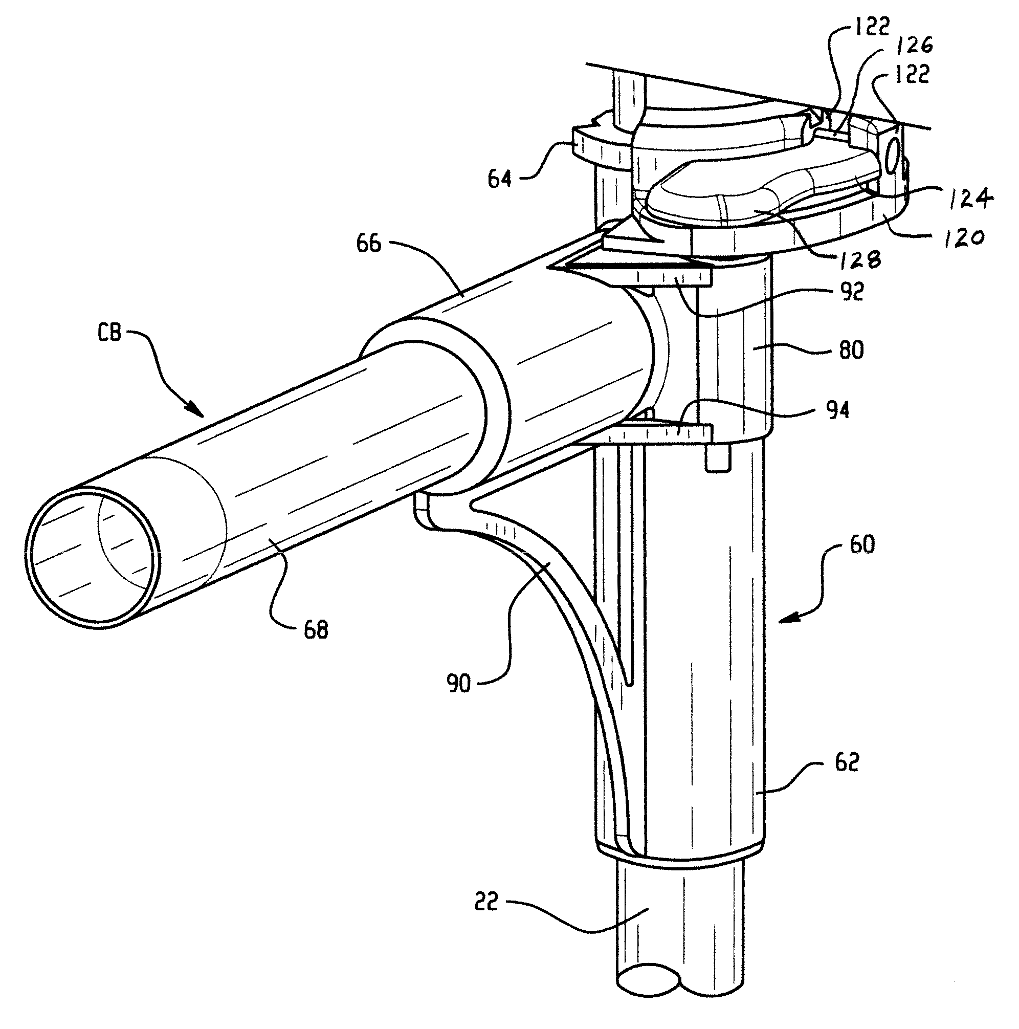
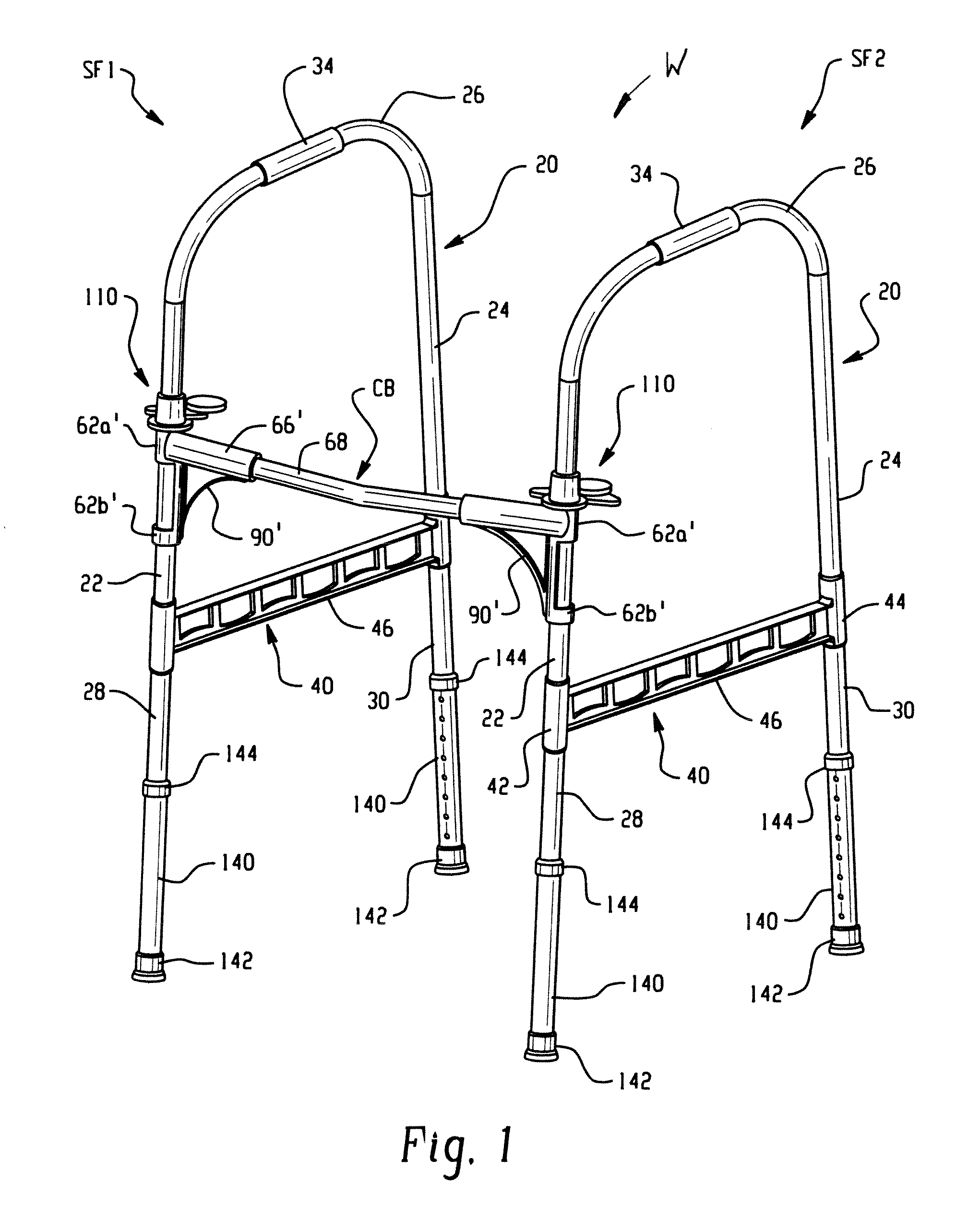
[0044]The drawings illustrate a preferred embodiment of the invention only, and are not intended to limit the invention. More particularly, FIG. 1 shows a walker W which includes a pair of side frames SF1 and SF2 interconnected by a front cross brace member or cross brace CB. The side frames are configured, as will be described below, to selectively pivot or rotate relative to the front cross brace to allow the walker to be collapsed or folded for storage or shipment. FIG. 1 illustrates the walker in the assembled, operative position where the side frames are disposed in generally parallel relation and extend generally perpendicularly from the front cross brace member. As will be appreciated, when folded or collapsed, the side frames are rotated inwardly, generally about a longitudinal axis of the front, first leg thereof, for positioning in planes generally parallel to that of the front cross brace member.

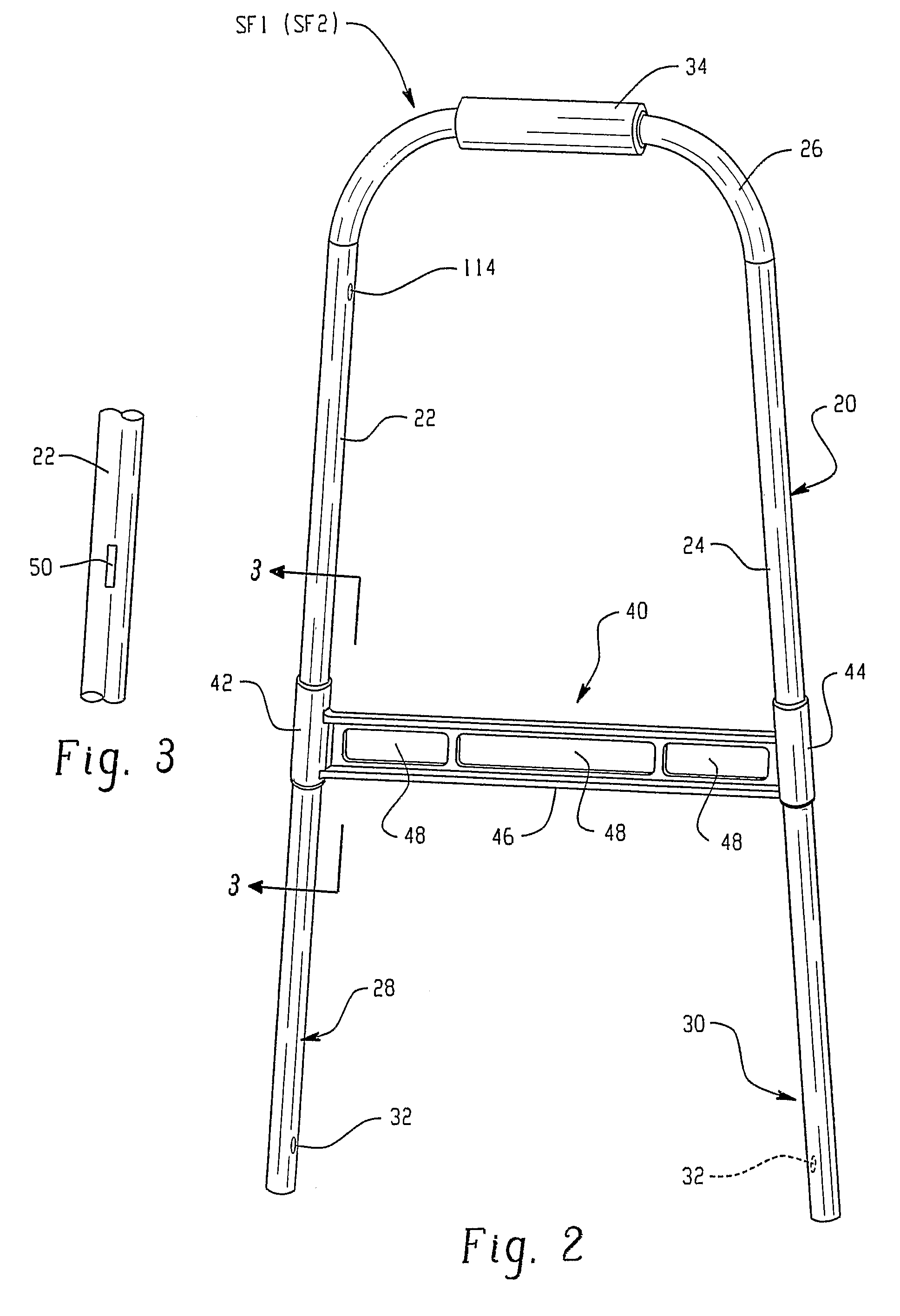
[0045]With continued reference to FIG. 1, and additional reference to FIG. 2,...


PUM

PropertyMeasurementUnit
pressuresaaaaaaaaaa
pressureaaaaaaaaaa
circumferenceaaaaaaaaaa

Abstract

A method of manufacturing a patient aid device, such as a walker (W), includes the steps of molding a polymer or plastic connector (60) over first and second metal structural members (22, CB) to maintain the structural members in a first geometrical relationship. After the plastic has cured, the method includes the step of rotating the first structural member or front leg (22) relative to the plastic connector (60) to form an integral hinge without any seam in the plastic. The resultant walker includes front legs (22) hinged via the connectors (60) at opposite ends of the front cross brace (CB). The front leg (22) and rear leg (24) of each side frame (SF1, SF2) of the walker are interconnected by a lower cross brace (40) that has plastic preferably molded about the entire periphery of each leg.

Description

[0001]This application is the national filing of and claims the benefit of PCT Patent Application Ser. No. PCT / US2005 / 011966, filed on 7 Apr. 2005, and claims the benefit of U.S. Provisional Patent Application Ser. No. 60 / 560,067, filed on Apr. 7, 2004, the disclosures of which are incorporated herein by reference.BACKGROUND OF THE INVENTION[0002]This invention relates generally to a durable product, and more particularly to a foldable product, and finds particular application as a patient aid device such as a walker, and a method of forming same. The invention is particularly applicable to a composite assembly for construction and use with foldable products of this type.[0003]Walkers, in general are well known and are used to assist ambulation and provide additional stability for persons who are, for example, elderly, infirm, have a disability, or are in rehabilitation. Conventional walker designs have four legs in contact with the ground to provide stability, and yet are sufficien...

Claims


Application Information

Patent Timeline
Patent Type & Authority Patents(United States)
IPC IPC(8): B29C45/14A61H3/00B29C65/64B29C65/70
CPCA61H3/00B29C45/14221B29C45/14754B29C45/14614A61H2201/0161Y10T29/49826B29K2705/00B29L2031/753
Inventor OBITTS, SHANEREICHLIN, JAMES
Owner OBITTS SHANE
Why Eureka
Try Eureka