Connector and electronic device having the same

Inactive Publication Date: 2014-03-25
HOSIDEN CORP
View PDF13 Cites 14 Cited by
  • Summary
  • Abstract
  • Description
  • Claims
  • Application Information

AI Technical Summary

Benefits of technology

[0009]In this aspect of the invention, the insulating resin molded portion covers the boundary between the body and the cover, the boundary between the body and the connecting portion of the contact, and the boundary between the cover and the connecting portion of the contact. Thus, the connector is thus capable of preventing water intrusion from between the cover and the body, between the body and the connecting portion of the contact, and between the cover and the connecting portion of the contact. Moreover, the connector can provide such waterproof property at low costs because the molded portion of the insulating resin can be manufactured by outsert molding or in a similar method.
[0011]In this aspect of the invention, the first molded portion covers the first blocking portion and bond the first blocking portion to the body; the second molded portion is filled in the first recess of the first end of the body to cover the second blocking portion and bond the second blocking portion to the body; and the third molded portion is filled in the second recess in the second end of the body. That is, the second and third molded portions are provided such as to hold the body in the second direction, this aspect of invention can improve the bonding strength of the molded portion to the cover and the body.
[0013]In this aspect of the invention, the fourth molded portion communicating with the third end of the first molded portion covers the third end of the body, and the fifth molded portion communicating with the fourth end of the first molded portion covers the fourth end of the body. That is, since the fourth and fifth molded portions hold the body in the third direction, the bonding strength of the molded portion to the cover and the body can be improved.
[0017]It is preferable at least one of the body, the cover and the molded portion be made of a polyamide resin. This aspect of the invention can improve waterproof property of the connector because polyamide resins generally exhibit favorably goods adhesion to other resin materials and metals. This aspect of the invention can also improve twisting strength of the connector because polyamide resins are superior to other resin materials in toughness.
[0018]The connector may further include a ring-shaped gasket to fit around the body. In this aspect of the invention, the ring-shaped gasket fitted around the body may be interposed between the connector and a housing of electronic device with the connector installed. Therefore, this aspect of the invention can prevent water intrusion from between the connector and the housing of the electronic device.

Problems solved by technology

Such a connector may allow water intrusion into the portable terminal when the portable terminal is inadvertently exposed to water in the state where the cover is not properly engaged with the connector.

Method used


Image

  • Connector and electronic device having the same
  • Connector and electronic device having the same
  • Connector and electronic device having the same

Examples


embodiment 1

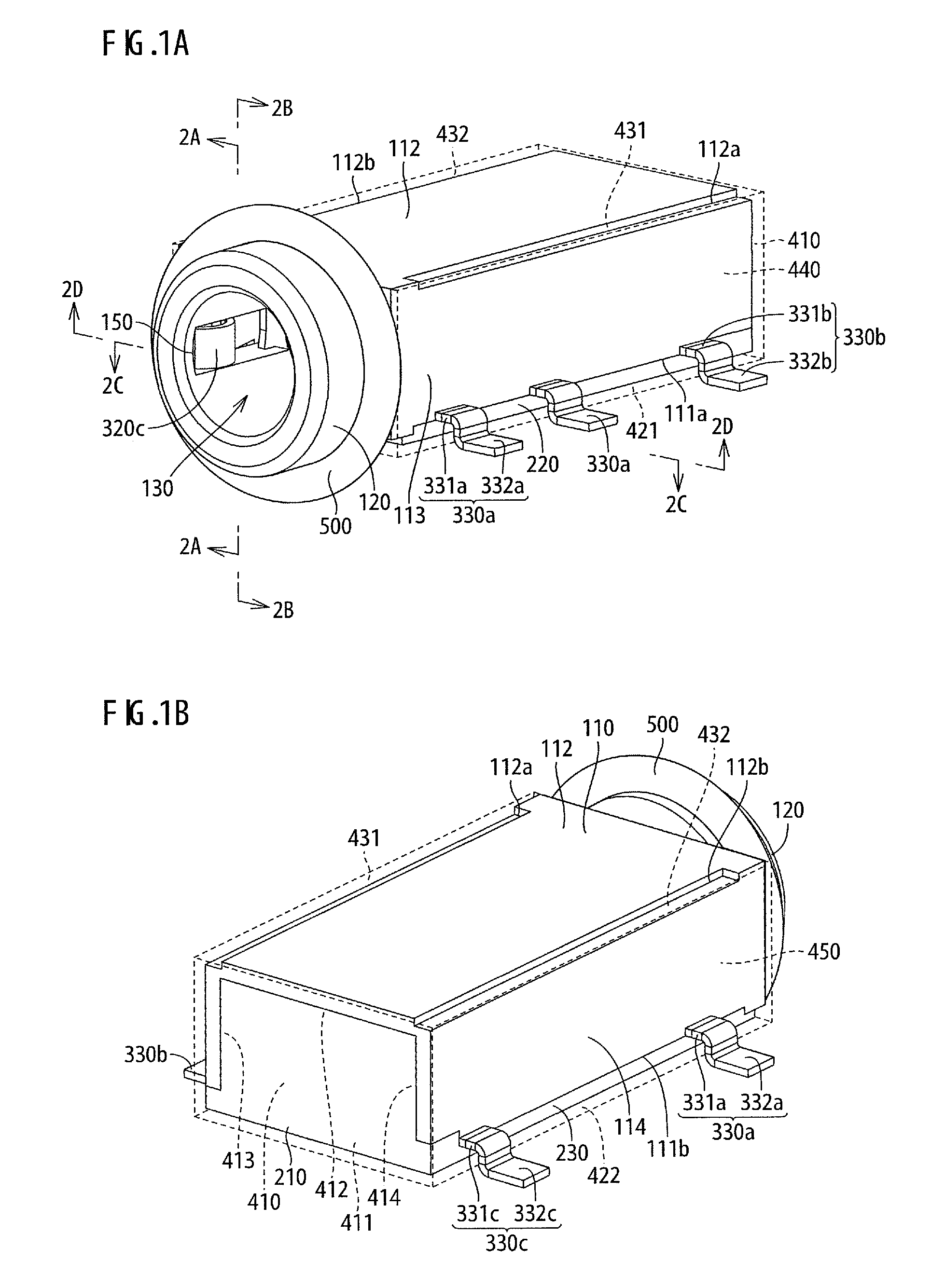
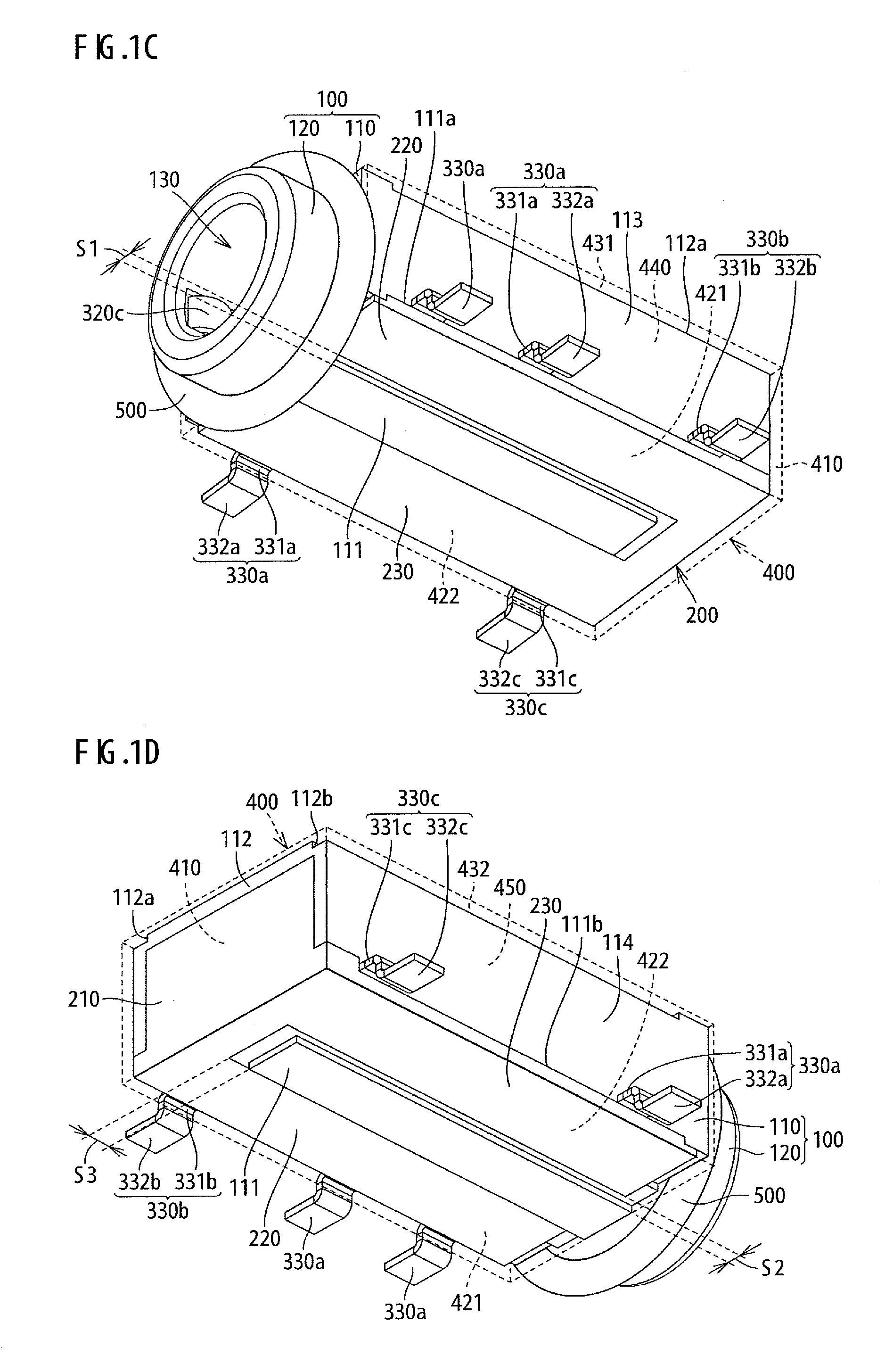
[0042]First, a connector in accordance with Embodiment 1 of the invention will be described with reference to FIG. 1A to FIG. 3B. The connector shown in FIG. 1A to FIG. 2B is a jack for mating with a plug (not shown). The connector includes a body 100, a cover 200, three contacts 300a, a contact 300b, a contact 300c, a molded portion 400, and a gasket 500. Each of these constituents of the connector will be described below in detail. It should be noted that FIG. 3A and FIG. 3B indicate X, Y, and Z directions, which are a width direction, a front-back direction, and a vertical direction, respectively, of the connector. The Y direction is orthogonal to the X direction, and the Z direction is orthogonal to the X and Y directions. The X, Y, and Z directions corresponds to a third direction, a first direction, and a second direction, respectively, in the claims, and the Y direction also corresponds to a longitudinal direction of the body 100 in the claims. The mating plug has a cylindric...

embodiment 2

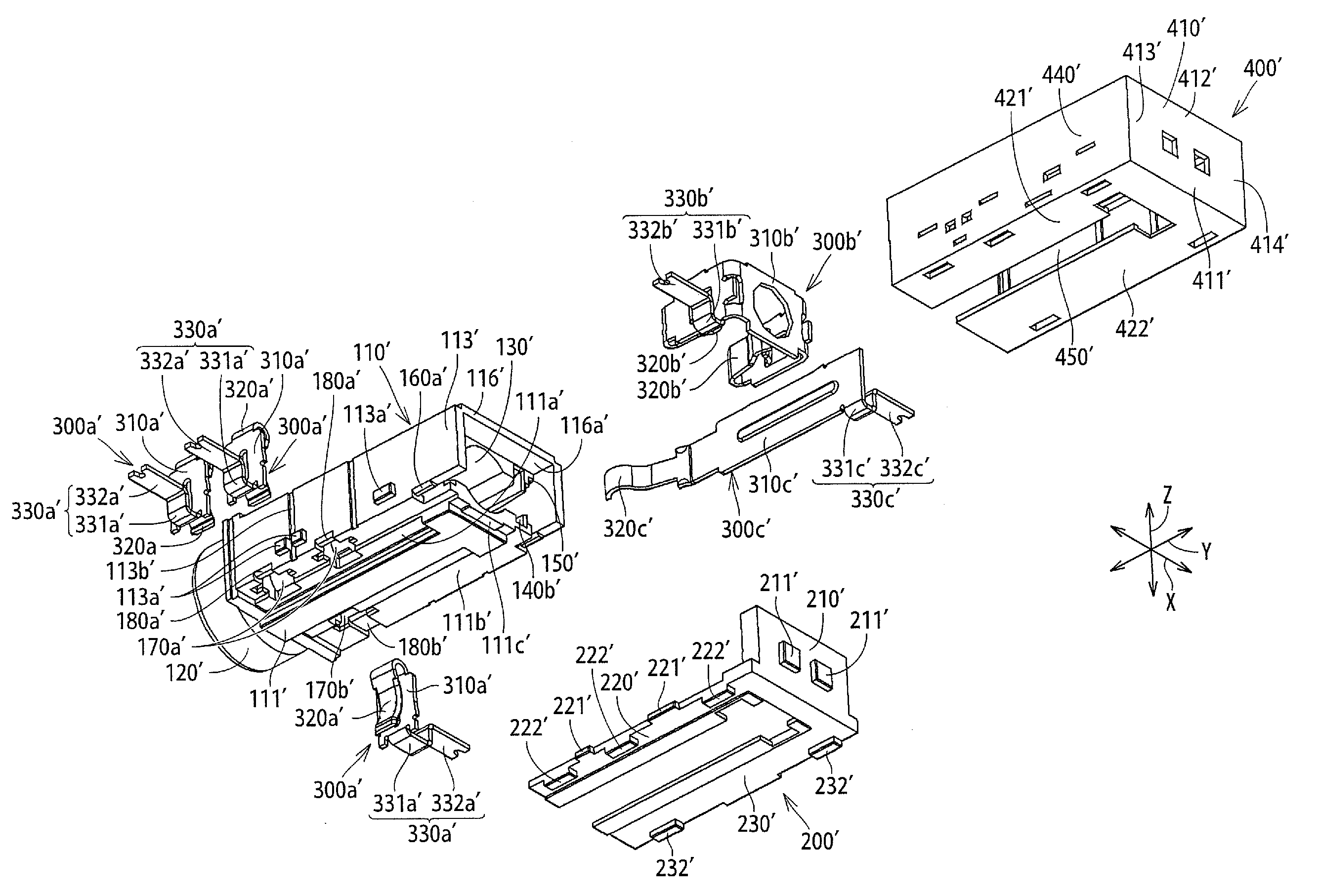
[0069]Next, a connector in accordance with Embodiment 2 of the invention will be described with reference to FIG. 4A to FIG. 6B. The connector shown in FIG. 4A to FIG. 5B is different from the connector in Embodiment 1 in that it is a mid-mount type connector to fit in a recess or a hole in a circuit board and be connected to the circuit board in this state. Specifically, to conform to the mid-mount type, the connector is different from the connector in Embodiment 1 in shape of a main body 110′ of a body 100′, a cover 200′, connecting portions 330a′ to 330c′ of contacts 300a′ to 300c′ and a molded portion 400′. Only these differences from Embodiment 1 will be described below in detail, and the overlaps will be omitted. As described above, a symbol _′_ is added to reference numerals referring to the body, the cover, the contacts and the molded portion of this connector to distinguish them from the body, the cover, the contacts and the molded portion of the connector of Embodiment 1.

[...


PUM


Abstract

The invention provides a connector including a body, a cover, a contact, and a molded portion. The body includes a connecting hole, and a housing hole or slit communicating with the connecting hole and being open to an outside of the body. The cover blocks the housing hole or slit of the body. The contact includes a fixed portion fixedly attached in the housing hole or slit of the body, a contact portion disposed in the connecting hole, and a connecting portion protruding from between the body and the cover to an outside of the body and the cover. The molded portion, formed of insulating resin, covers and blocks at least a boundary between the body and the cover, a boundary between the body and the connecting portion of the contact, and a boundary between the cover and the connecting portion of the contact.

Description

[0001]The present application claims priority under 35 U.S.C. §119 of Japanese Patent Application No. 2011-201038 filed on Sep. 14, 2011, the disclosure of which is expressly incorporated by reference herein in its entity.BACKGROUND OF THE INVENTION[0002]1. Technical Field[0003]The present invention relates to connectors and electronic devices provided with the connectors.[0004]2. Background Art[0005]There is known a connector as disclosed in JP Publication No. 2004-87185 serving as an earphone jack for use in portable terminals such as smartphones. The connector is provided with a cover fitting thereover to prevent water intrusion into the portable terminal through the connector.SUMMARY OF INVENTION[0006]Such a connector may allow water intrusion into the portable terminal when the portable terminal is inadvertently exposed to water in the state where the cover is not properly engaged with the connector.[0007]In view of the above circumstances, the invention is devised to provide a...

Claims


Application Information

Patent Timeline
Patent Type & Authority Patents(United States)
CPCH01R13/5213H01R24/58H01R2107/00H01R13/52H04R1/10H05K5/03
Inventor NAGATA, TAKAYUKISASAKI, DAISUKE
Owner HOSIDEN CORP
Why Eureka
Try Eureka