
Papermaking Machine Employing An Impermeable Transfer Belt, and Associated Methods

a transfer belt and papermaking machine technology, applied in the field of papermaking machines, can solve the problems of torn webs, ineffective use of such modified belts for processing light-weight tissue webs at high speeds, and torn webs, and achieve the effect of sufficient wet strength and higher sheet caliper

Active Publication Date: 2010-12-30
VALMET AB
View PDF11 Cites 21 Cited by
  • Summary
  • Abstract
  • Description
  • Claims
  • Application Information

AI Technical Summary

Benefits of technology

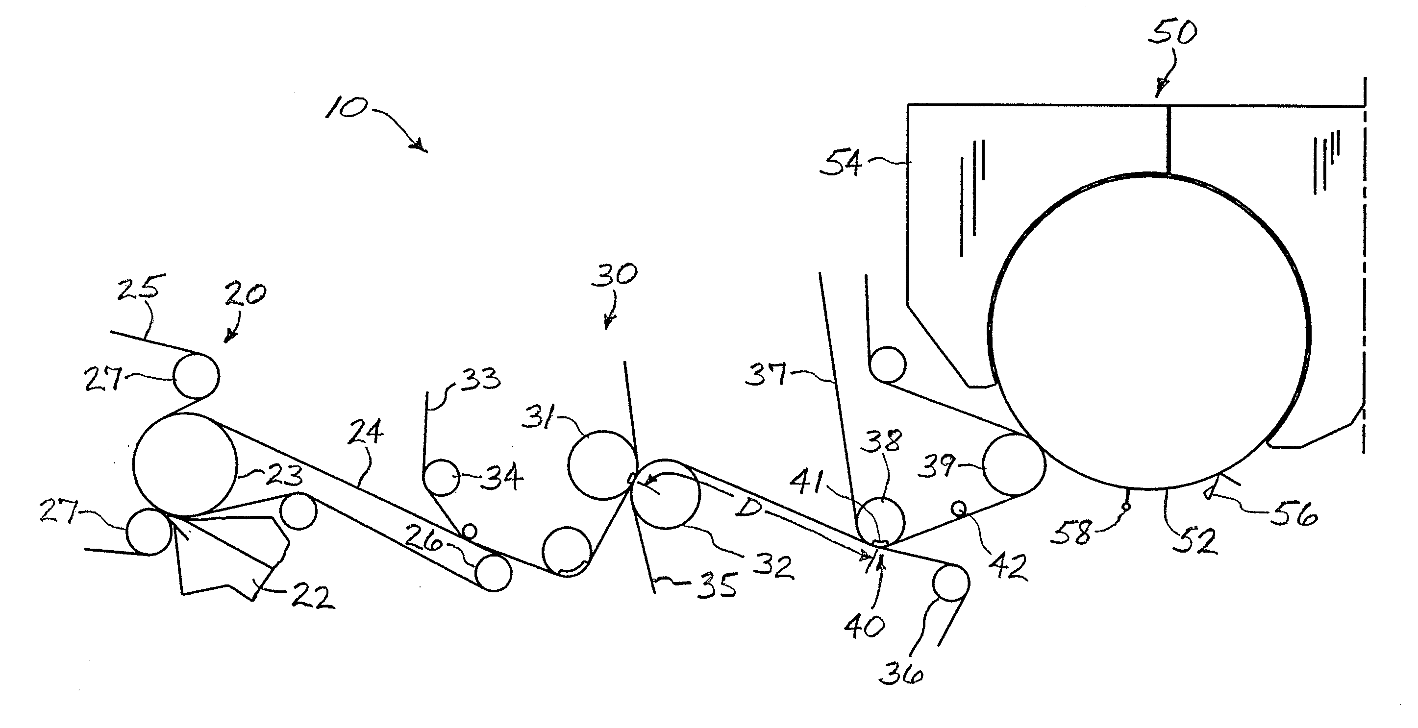
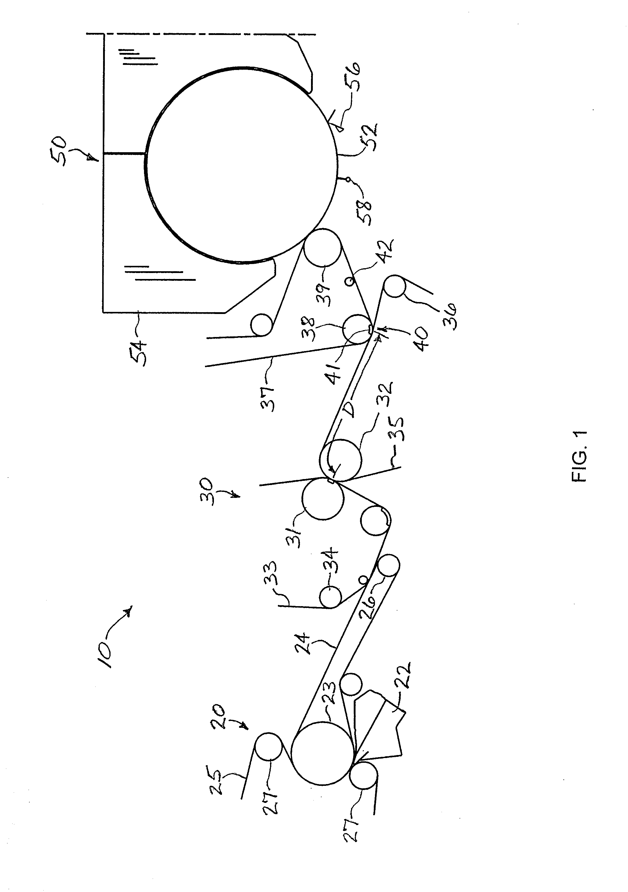
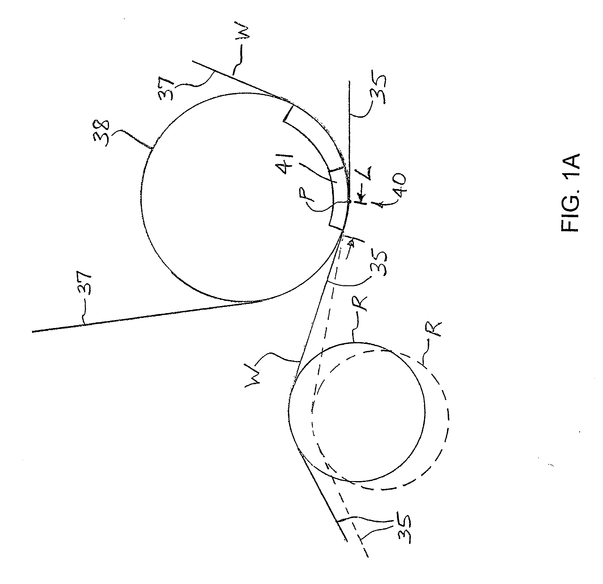
[0014]In accordance with another aspect of the disclosure, a method of configuring and operating a papermaking machine for making a paper web is provided. The method comprises steps of using a forming section to form a wet paper web, using a press section as previously described to press and dewater the wet paper web, and using a drying section to dry the paper web. The method further comprises the step of selecting the distance D between the press nip and the transfer point taking into account at least a linear speed of the transfer belt, a basis weight of the paper web, and a roughness characteristic of the surface of the transfer belt in contact with the wet paper web, such that within the distance D a thin water film between the paper web and the surface of the transfer belt at least partially dissipates to allow the paper web to be separated from the transfer belt without breaking.
[0023]The transfer of the web to the texturizing fabric can include a “rush” transfer or a “draw” transfer. Rush transfers are transfers where the receiving fabric (downstream fabric) is traveling at a machine speed that is lower than the machine speed of the upstream fabric. Draw transfers are the opposite, i.e., the receiving fabric is traveling at a machine speed that is higher than the upstream fabric. Depending upon the nature of the texturizing fabric, rush transfer can aid in creating higher sheet caliper. When used, the level of rush transfer can be about 5 percent or less.
[0024]Fabric cleaning can be particularly advantageous, particularly using a method that leaves a minimal amount of water on the fabric (about 3 gsm or less). Suitable fabric cleaning methods include air jets, thermal cleaning, and high pressure water jets. Coated fabrics, which clean more-easily than non-coated fabrics, can be employed.

Problems solved by technology

While effective for relatively heavy basis weight webs, the use of such modified belts still is not effective for processing light-weight tissue webs at high speeds necessary for commercial applications because of the difficulty associated with transferring low basis weight wet webs, which have virtually no strength.
Attempts to remove the fragile tissue web from the belt surface often result in torn webs.

Method used


Image

  • Papermaking Machine Employing An Impermeable Transfer Belt, and Associated Methods
  • Papermaking Machine Employing An Impermeable Transfer Belt, and Associated Methods
  • Papermaking Machine Employing An Impermeable Transfer Belt, and Associated Methods

Examples


example 1

Comparative

[0075]A twin-wire former was used to make a lightweight paper sheet of less than 20 gsm. The papermaking machine speed was 600 m / min. The wet paper web was transferred to a felt and partially dewatered with vacuum to a dryness of about 25% dry solids content. The web was then compressively dewatered with an extended nip press at a load of 400 kN / m, with a peak pressure of 4 MPa, to a dryness of about 40%. The felt and tissue web were pressed against a belt similar to an Albany T2 transfer belt with a roughness Ra of about 6 micrometers as measure by stylus profilometry. Upon exiting the press the sheet was attached to the transfer belt. The transfer belt and paper traveled around the press roll and were then contacted with a texturizing fabric (style 44GST) manufactured by Albany. The distance from the press to the vacuum roll was about 2.4 meters. The texturizing fabric was in contact with the tissue web for a distance of about 25 mm after it came into contact with the v...

example 2

Comparative

[0076]The conditions of Example 1 were repeated with a higher machine speed of 1000 m / min. The transfer of the tissue web to the fabric failed. From these trials, it was determined that the Albany T2 type of belt is not suitable for high-speed manufacture of low basis-weight paper in the type of process described herein.

example 3

[0077]The conditions of Example 1 were repeated with a transfer belt similar to an Albany LA particle belt with a roughness of 3 micrometers. The tissue web transferred to the fabric at speeds up to 1200 m / min. Product samples were taken at 600 meters / minute because of limitations with the reel, but the properties of sheets produced at higher speeds are believed to be very similar. The properties of the tissue were as follows:

Basis weight (bone dry)g / m216.9Caliperμm283Bulkcm3 / g16.7Stretch MD%39.8Stretch CD%12.4Tensile MDN / m81Tensile CDN / m41

[0078]This Example illustrates that the use of a particle belt as the transfer belt enables transfer of the web at higher speeds than conventional transfer belts.


PUM


Abstract

A papermaking machine for making paper includes a forming section, a press section, and a drying section. The paper web is pressed between two press members while enclosed between a press felt and a transfer belt having non-uniformly distributed microscopic depressions in its surface, the web following the transfer belt from the press to a transfer point at which the web is transferred via a suction transfer device onto a structuring fabric, the web then being dried on a drying cylinder. The transfer point is spaced a distance D from the press nip selected based on machine speed, a basis weight of the web, and the surface characteristics of the transfer belt, such that within the distance D a thin water film between the web and the transfer belt at least partially dissipates to allow the web to be separated from the transfer belt.

Description

CROSS-REFERENCE TO RELATED APPLICATIONS[0001]This application is a divisional of currently pending application Ser. No. 11 / 924,835 filed Oct. 25, 2007, the entire disclosure of which is hereby incorporated herein by reference.BACKGROUND OF THE INVENTION[0002]The present disclosure relates to papermaking. More particularly, the present disclosure relates to a papermaking machine for making a paper web, and associated methods.[0003]Many attempts to combine the bulk-generating benefit of throughdrying with the dewatering efficiency of wet-pressing have been disclosed over the past 20 years. An example of such a process is disclosed in U.S. Pat. No. 6,287,426 issued Sep. 11, 2001 to Edwards et al., which is herein incorporated by reference. This process utilizes a high pressure dewatering nip formed between a felt and an impermeable belt to increase the wet web consistency to about 35 to 50 percent. The web adheres to and follows the impermeable belt as it exits the press nip. The dewat...

Claims


Application Information

Patent Timeline
Patent Type & Authority Applications(United States)
IPC IPC(8): D21F11/00D21G9/00
CPCD21F7/08D21F7/086D21F11/006D21F3/045D21F11/14D21F3/02D21F3/04
Inventor KLERELID, INGVAR BERNDT ERIKIVARSSON, HANSRAGARD, JOHAN ULFHADA, FRANK STEPHENBEUTHER, PAUL DOUGLASHOLZ, JEFFREY DEAN
Owner VALMET AB
Learn More