Wire reel structure

Inactive Publication Date: 2010-12-30
KUO CHIN CHANG
View PDF7 Cites 5 Cited by
  • Summary
  • Abstract
  • Description
  • Claims
  • Application Information

AI Technical Summary

Benefits of technology

[0010]The casing body includes a central pillar for containing the reel unit therein. The signal line unit includes a first signal line and a second signal line, and the first signal line is passed to the reel unit and wound at an external side of the reel unit. The second signal line is connected to the first signal line and wound at an external side of the central pillar, wherein the first signal line and the second signal line are signal lines with different deformation curves, and the second signal line has a greater flexibility than the flexibility of the first signal line.
[0011]The advantages

Problems solved by technology

With this drawback, the aforementioned wire reel is generally used in stereo devices such as earphones and voice boxes only, but its use is not suitable for computer peripherals.
However, this conventional wire reel has the drawback that the cable 11′ may be broken easily due to the design of the wire reel structure, such that the using life is reduced.
Since the cable 11 may be folded i

Method used


Image

  • Wire reel structure
  • Wire reel structure
  • Wire reel structure

Examples


Example

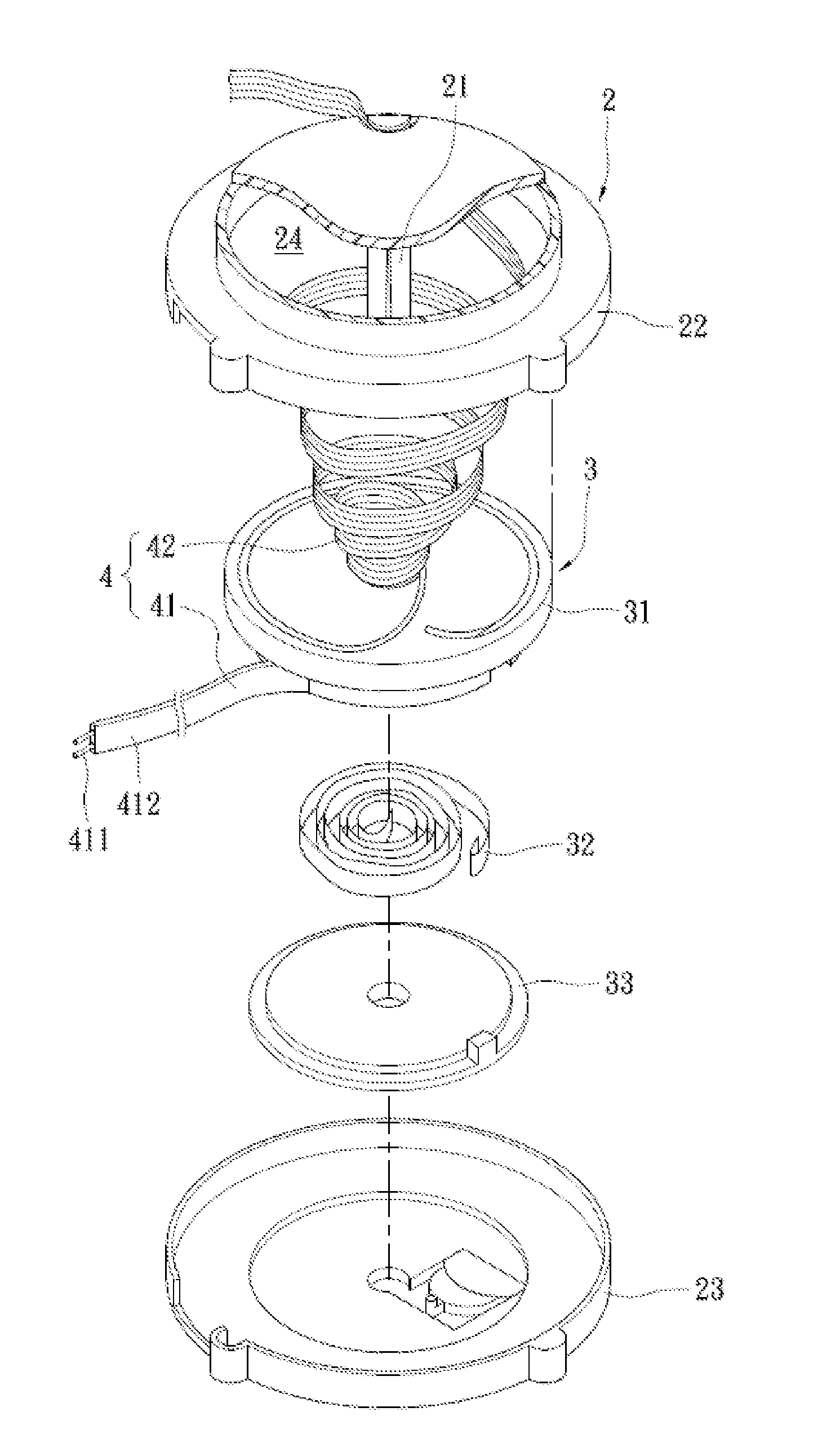
[0019]With reference to FIG. 4 for a wire reel structure of the present invention, the wire reel structure comprises a casing body 2, a reel unit 3 and a signal line unit 4.

[0020]The casing body 2 includes a central pillar 21 installed therein, and further includes a first casing 22 and a second casing 23 engaged with each other, wherein central pillar 21 is formed by extending from either the first casing 22 or the second casing 23.

[0021]The reel unit 3 is contained in the casing body 2, and the central pillar 21 is passed through the reel unit 3. The reel unit 3 includes a turntable 31, a coil spring 32 contained in the turntable 31, and a cover disc 33 covered onto the turntable 31, wherein an external end portion of the coil spring 32 is latched to the turntable 31, and an internal end portion of the coil spring 32 is latched to the central pillar 21 for driving the turntable 31 to rotate automatically. The central pillar 21 is passed through the turntable 31, the coil spring 32...


PUM


Abstract

A wire reel structure includes a casing body, a reel unit and a signal line unit. The casing body includes a central pillar, and the reel unit is contained in the casing body. The signal line unit includes first and second signal lines, and the first signal line is passed into reel unit and wound at an external side of the reel unit. The second signal line is connected to the first signal line and wound at an external side of the central pillar. The first and second signal lines are signal lines with different deformation curves, and the second signal line has a greater flexibility than the flexibility of the first signal line, such that the second signal line will not be folded reversely when wire sections in the casing body are rotated.

Description

FIELD OF THE INVENTION[0001]The present invention relates to a wire reel, in particular to a wire reel structure for coiling signal lines made of different materials with different flexibilities.BACKGROUND OF THE INVENTION[0002]To manage long signal lines, a wire reel mechanism is generally provided for automatically coiling data, audio / video and control signal transmission lines such as USB signal transmission lines of computer peripherals, and such wire reel mechanism usually includes a reel unit driven by a coil spring for its rotation, and the coil spring produces an elastic torque to drive the reel unit to rotate and coil the signal line automatically. In the process of pulling out the signal line, the reel unit keeps on rotating, such that the coil spring produces an elastic torque in a reverse direction, and when the signal line is no longer pulled, the coil spring will start driving the reel unit to coil the signal line automatically. The wire reel mechanism generally comes ...

Claims


Application Information

Patent Timeline
IPC IPC(8): B65H75/48B65H75/44
CPCB65H75/4452H02G11/02B65H2701/34A61P35/00
Inventor KUO, CHIN-CHANG
Owner KUO CHIN CHANG
Why Eureka
Try Eureka