

Aircraft seat arrangement including table
- Summary
- Abstract
- Description
- Claims
- Application Information
AI Technical Summary
Benefits of technology
Problems solved by technology
Method used
Image

Examples
Embodiment Construction
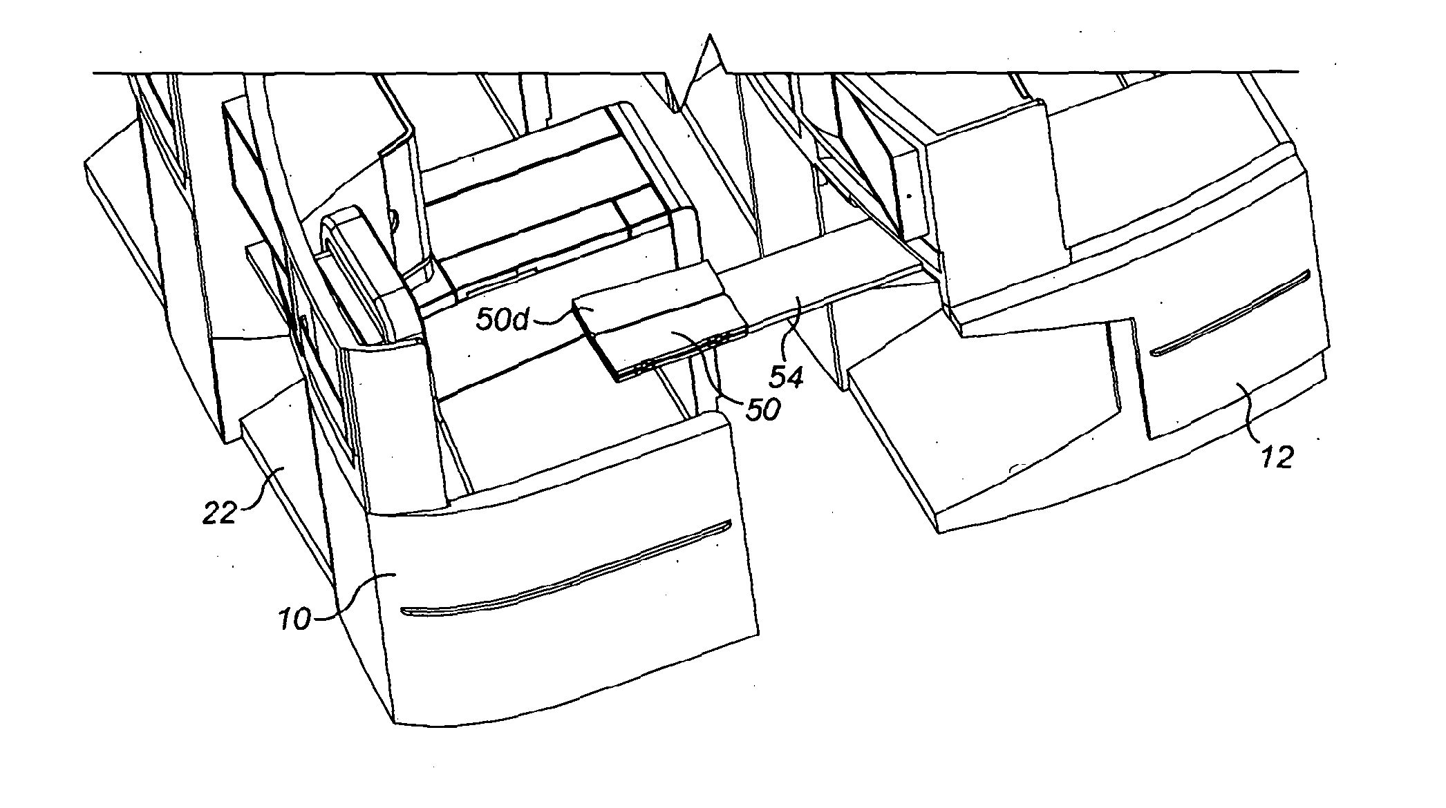
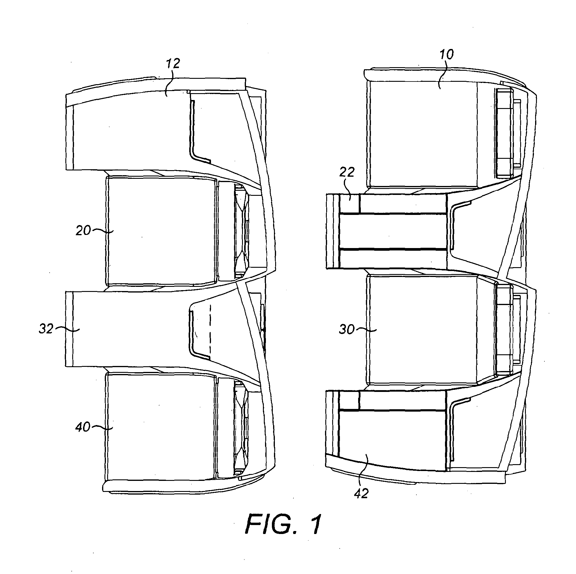
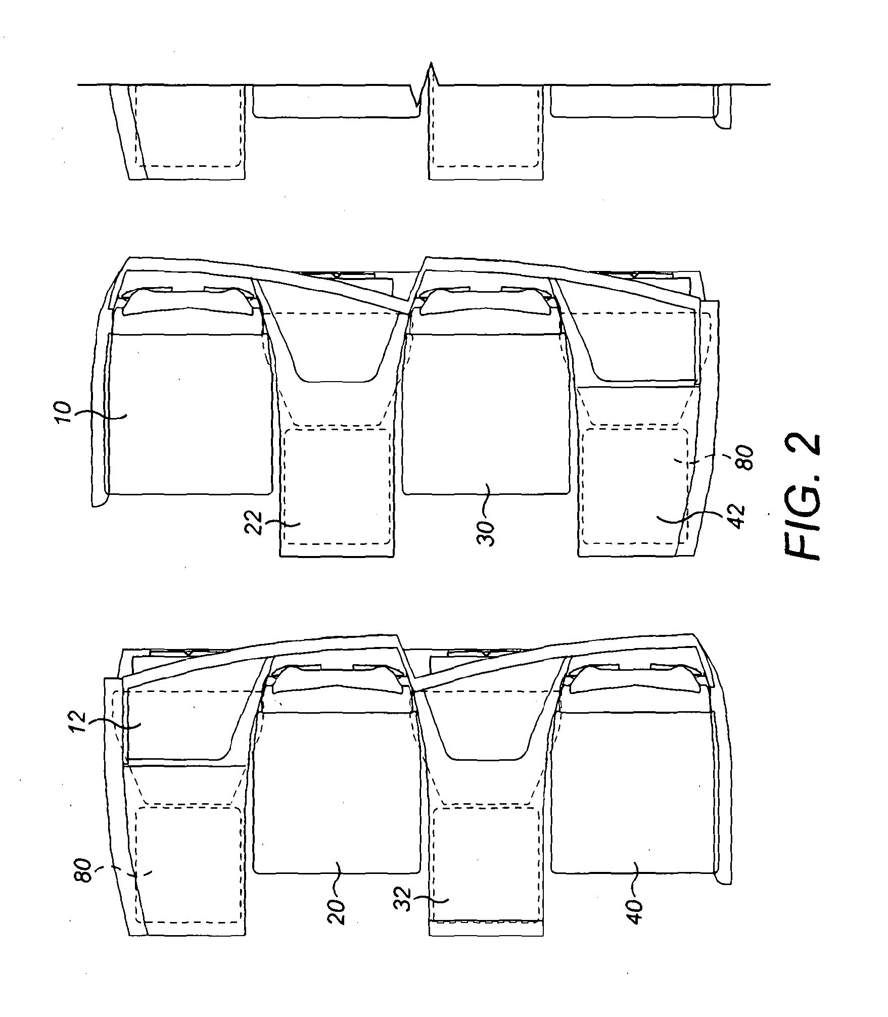
[0082]FIGS. 1 to 13c and 18 show an aircraft seat arrangement for a premium class (premium economy or business class for example) comprising a table moveable between a stowed position and a plurality of deployed positions. FIGS. 1 and 2 show, in plan views, four seats and four consoles. There is therefore a first seat 10 aft of a first console 12, a second seat 20 fore of a second console 22, a third seat 30 aft of a third console 32 and a fourth seat 40 fore of a fourth console 42. There is therefore a first row formed by (in order from one end of the row to the other) the first seat 10, the second console 22, the third seat 30, and the fourth console 42, and a second row formed by (in order from one end of the row to the other) the first console 12, the second seat 20, the third console 32, and the fourth seat 40. The second row is in front of the first row. Thus, the first seat 10 is located directly aft of the first console 12 and is directly adjacent to the second console 22.
[0...
PUM
 Abstract
Description
Claims
Application Information