Method and device for sandblasting, especially removing in a precise manner and/or compacting and/or coating solid surfaces

Inactive Publication Date: 2006-02-14
PIEPER INNOVATIONSGMBH
View PDF21 Cites 12 Cited by
  • Summary
  • Abstract
  • Description
  • Claims
  • Application Information

AI Technical Summary

Benefits of technology

[0008]The invention has as its object to so improve a method and an apparatus of the kind described at the outset that the jet velocity is significantly increased and in spite of that increase in jet velocity, the amount of energy with whic

Problems solved by technology

For the removal or leveling of harder surfaces, like for example solder and weld seams, however, the jet velocity which is produced is too low so that the known method is uneconomical.
Especially in the case of metallic lacquering of automobile body parts, defect locations can arise in the application of the paint which above all have their origins in point-like or flat inclusions in the clear lacque

Method used


Image

  • Method and device for sandblasting, especially removing in a precise manner and/or compacting and/or coating solid surfaces
  • Method and device for sandblasting, especially removing in a precise manner and/or compacting and/or coating solid surfaces
  • Method and device for sandblasting, especially removing in a precise manner and/or compacting and/or coating solid surfaces

Examples


Example

EXAMPLE 1

[0037]From a lacquering or painting of an automobile body part, defects are to be removed by the method according to the invention. FIG. 3 shows a variant of the apparatus according to the invention with which the method according to the invention is carried out.

[0038]The apparatus of FIG. 3 comprises substantially a blast chamber 7 having a blast lance 14 arranged therein, a metering worm 11 which is connected with the jet lance 14 by a flexible hose 13, a supply vessel 44 or the blast agent 2 which is connected with the metering worm 11 by means of a charging duct 45, a suction fitting 21 which at one end opens into the blast chamber 7 and at its opposite end via a hose 6 extends to a separator 22, and a suction unit 3 whose suction side is connected with the latter.

[0039]The blast chamber 7 is, as FIG. 4 shows, formed from a cylindrical sleeve body 23 which has an inner receiving space 24. In the inner receiving space a thin jet lance 14 can be shoved into the cylindrica...

Example

EXAMPLE 2

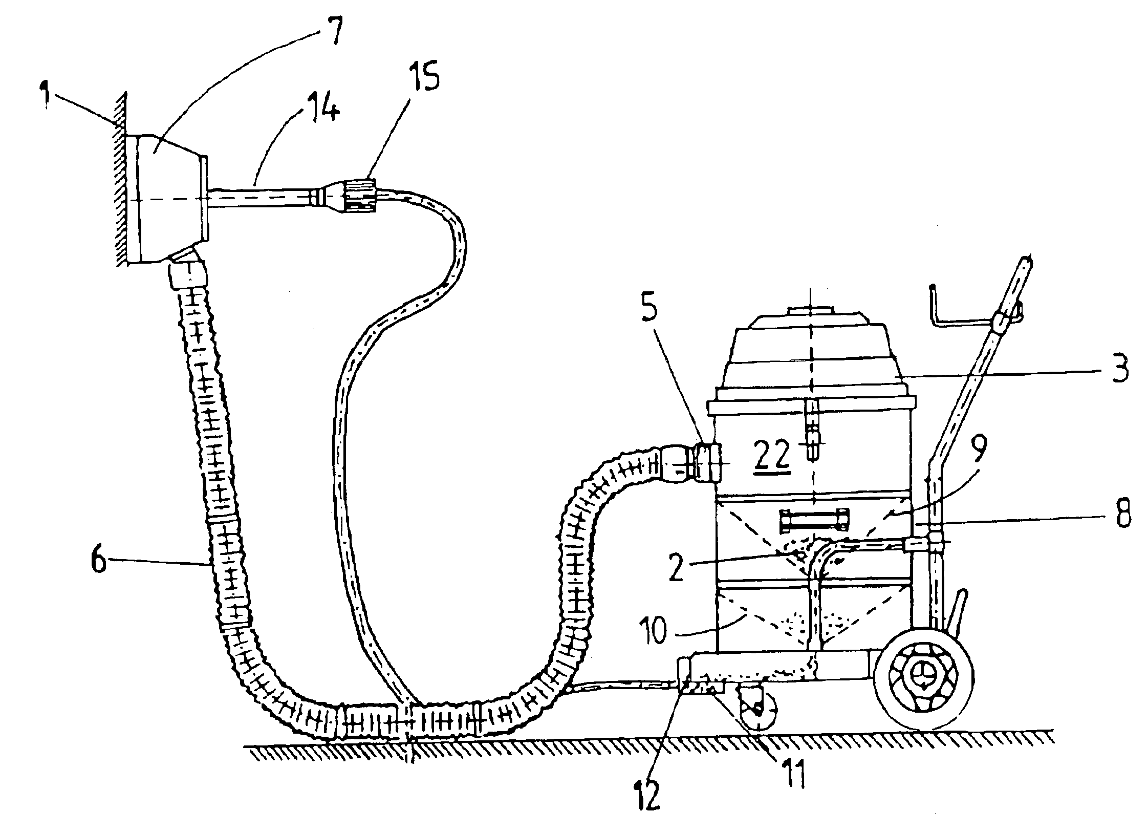
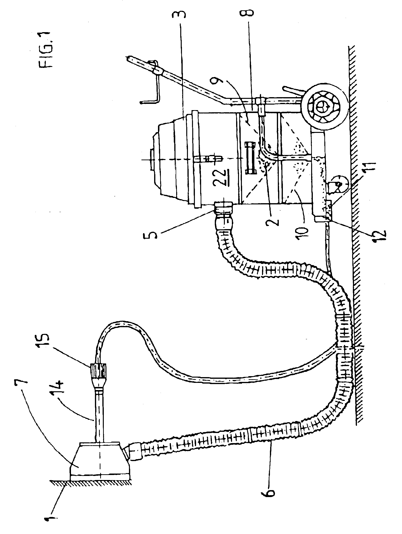
[0049]With the method of the invention, a solder seam 36 is leveled [planed] and smoothed between two bent sheet metal plates 48. FIG. 5 shows an apparatus according to the invention for the smoothing such solder seams and which in its construction corresponds to the previously described system construction.

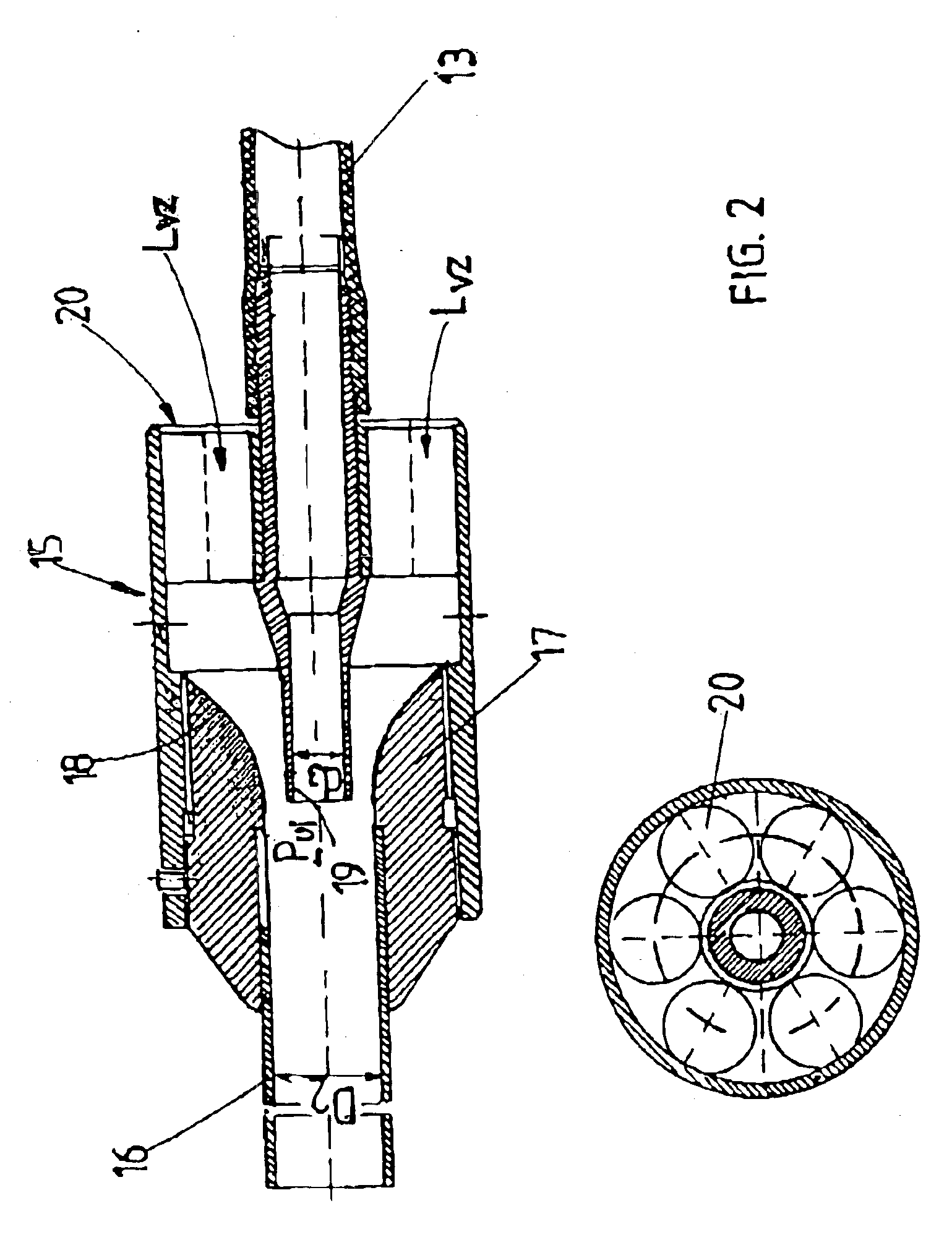
[0050]In FIG. 6 the blast chamber 7 has been shown which comprises a body 37 which can be set upon the surfaces to be treated of the solder seam 36, a jet lance 14 which extends in the body 37 up to close to the solder seam 36 at an angle a to a normal N of the surface of the solder seam 36, a mask 38 which closes the body 37 and has an outlet opening 39 for the sandblasting medium which corresponds to the solder seam and is gap shaped, and a suction fitting widening in a funnel shape. The jet lance 14 has a gap shaped end 41 whose longitudinal dimension corresponds generally to the longitudinal dimension of the surface to be treated of the solder seam 36. This ensures t...

Example

EXAMPLE 3

[0054]A contaminated concrete layer from a concrete surface is removed by the method according to the invention. The construction of the apparatus according to the invention corresponds to that has been described previously in principle. The airstream generated by the suction unit 3 of about 3000 to 5000 m3 / h is distributed to a multiplicity of jet lances 14 oriented with respect to one another in a fan-like pattern and supplied with respective separate hoses 13. Each of the hoses 13 is provided with an injector 15 which impart an additional energy pulse to the carrier air flow / sandblasting agent mixture for significant increase in the blast velocity. All of the jet lances 14 are arraigned in a common blast chamber 7 which can be shifted on the concrete surface. The suction unit 3 produces a suction pressure of 400 to 500 mbar and blast velocity of about 300 m / s can be reached.

[0055]The sandblasting agent-concrete particle mixture passes over the hose 6 into the separator 2...


PUM

PropertyMeasurementUnit
Pressureaaaaaaaaaa
Angleaaaaaaaaaa
Angleaaaaaaaaaa

Abstract

The invention relates to a method and device for sandblasting, especially removing in a precise manner and/or compacting and/or coating solid surfaces, such as removing defective spots of paint from coats of lacquer, smoothing out soldered and welded joints, removal of contaminated concrete coatings or rust coatings, hardening, planing or coating metal surfaces, wherein a sandblasting agent is added by means of gravity and/or due to the effect of an injector to a carrier air flow produced by an underpressure, conveyed in a flexible hose- line system (13) to a jet lance (14) before being guided via a processing surface subject to low pressure by a sandblasting chamber, whereupon it is returned in the air flow, purified and returned to the circuit, whereby acceleration of the sandblasting agent is produced by the low pressure and the sandblasting chamber is displaced from one processing surface to another. The aim of the invention is to increase the sandblasting speed in a significant manner while at the same time economically adjusting the amount of power furnished to the processing surface for various wide-ranging fields of application using as little power as possible yet providing high flexibility and ecologically compatible recovery and reutilization of the sandblasting means. In order to achieve this, the sandblasting agent receives at least one additional energy pulse from a gas flow which is placed at least under atmospheric pressure and suctioned by the low pressure in order to reach a final speed which is significantly greater than the speed of the carrier air flow downstream from the area where dosing occurs. The final speed makes it possible to adjust the amount of power applied to the surface to be processed according to the following parameters: type and forms of the surface to be processed and the sandblasting agent, degree in which the carrier air flow is charged with the sandblasting agent, low pressure in the carrier air flow, and time and temperature of sandblasting.

Description

CROSS REFERENCE TO RELATED APPLICATIONS[0001]This application is the US national stage of PCT / DE02 / 00252 filed 22 Jan. 2002 and based upon German national application 10102924.1 itself filed 23 Jan. 2001 under the International Convention.FIELD OF THE INVENTION[0002]The invention relates to a method for sandblasting of solid surfaces, especially for exact-shape removal and / or compaction and / or coating, for example, the removal of paint from defective paint locations, for the smoothing of solder and weld seams, for the removal of contaminated concrete layers or rust layers, for the hardening or leveling of metal surfaces, in which a blast medium is metered into a carrier air stream produced by suction by means of gravity and / or an injection effect, is supplied by a flexible piping system to a jet lance and is directed against a surface to be treated in a blast chamber maintained under subatmospheric pressure and is from there returned in an air stream, cleaned and optionally fed in a...

Claims


Application Information

Patent Timeline
IPC IPC(8): B24C1/00B24C3/16B24C5/04B24C1/04B24C3/06B24C9/00B24C11/00
CPCB24C1/04B24C1/086B24C9/006B24C5/04B24C3/065Y02P70/10
Inventor PIEPER, GERARD
Owner PIEPER INNOVATIONSGMBH
Why Eureka
Try Eureka