
Process for producing pneumatic tire

a pneumatic tire and process technology, applied in the field of pneumatic tire production, can solve the problems of small amount of pressing force acting on the inner circumferential surface of the green tire, difficult to correct, and limited improvement in the uniformity of the vulcanized tire, so as to improve the uniformity of the tire to be produced, improve the gas-barrier properties, and improve the effect of uniformity

Inactive Publication Date: 2010-12-30
THE YOKOHAMA RUBBER CO LTD
View PDF5 Cites 2 Cited by
  • Summary
  • Abstract
  • Description
  • Claims
  • Application Information

AI Technical Summary

Benefits of technology

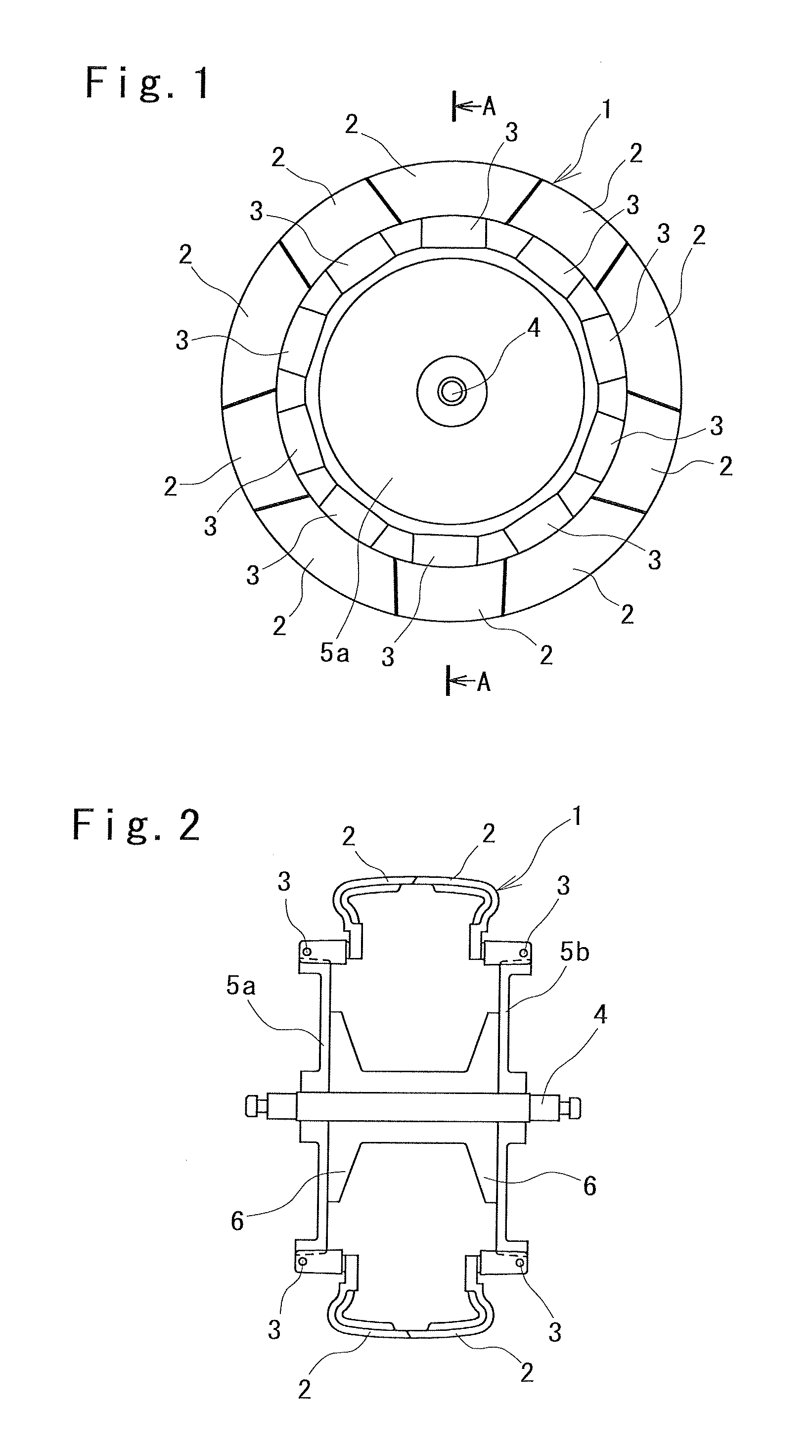
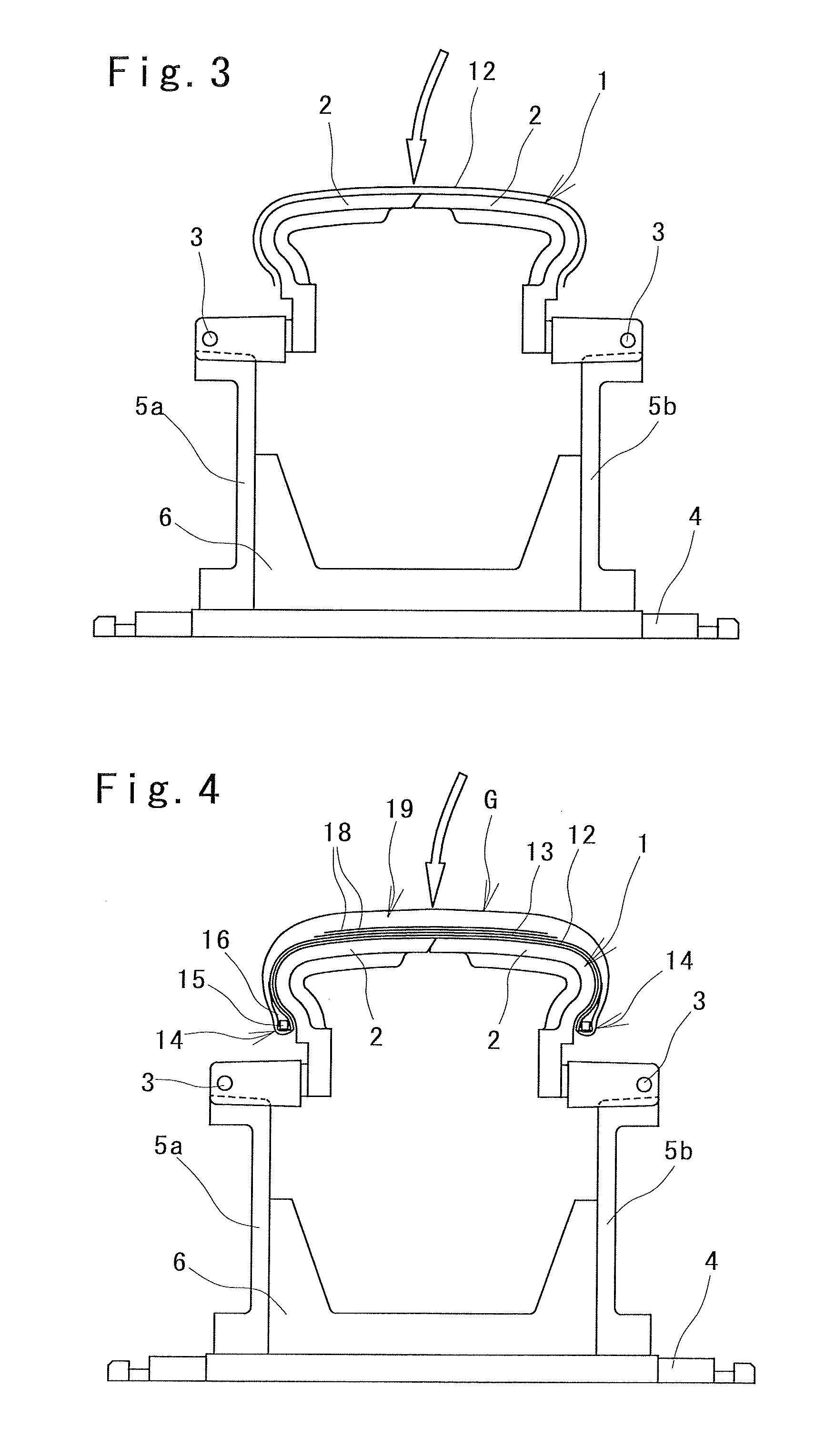
[0010]According to a process for producing a pneumatic tire of the present invention, a green tire is formed by stacking tire components on a film which is placed on an outer circumferential surface of a cylindrical rigid inner die formed of a plurality of split parts and which is made of a thermoplastic resin or a thermoplastic elastomer composition. The green tire is then placed in a vulcanizing mold together with the rigid inner die, the vulcanizing mold provided in a vulcanizing apparatus. Thereafter, the rigid inner die and the vulcanizing mold are heated to a given temperature. Then, the film is inflated by applying a pressure to the film from an inner circumferential side, and the green tire is then vulcanized. Accordingly, unvulcanized rubber of the tire components is pressed toward an inner circumferential surface of the vulcanizing mold and then flows in the circumferential direction. Thereby, even if unevenness exists in the volumes of the tire components, the unevenness is corrected. Thus, it is made possible to improve the uniformity of the tire to be produced.
[0011]The film is made to function as the conventional bladder as described above and also to serve as an inner layer of the tire by tightly bonding the film to an inner circumferential surface of the tire during the vulcanization of the green tire. The film is formed of the thermoplastic resin or the thermoplastic elastomer composition, so that the film is light in weight and has good gas-barrier properties as compared with a conventional inner layer made of butyl rubber. Thus, the produced tire can obtain lightweight and excellent air permeation prevention performance.
[0012]Moreover, the formed green tire is placed in the vulcanizing mold together with the rigid inner die, so that an operation to remove the green tire from the making drum in the case of the conventional method is no longer necessary. Further, the green tire can be easily placed at a predetermined position in the vulcanizing mold. In addition, the film serving as the inner layer can also function as a remover between the inner circumferential surface of the tire and the outer circumferential surface of the rigid inner die. Thus, the additional operation such as application of a remover is no longer necessary. The production steps can be thus reduced as described above, and the productivity can be thereby improved.

Problems solved by technology

During the vulcanization, however, the green tire is only pressed by the vulcanizing mold from the outer side, so that the amount of pressing force acting on the inner circumferential surface of the green tire becomes small.
Accordingly, for example, if the volumes of tire components are uneven in the inner circumferential surface of the tire, it is difficult to correct the unevenness, and an improvement in uniformity of the vulcanized tire is thus limited.
This presents a problem of reduced quality of the external appearance.
For this reason, such an inner layer is disadvantageous in reducing the weight of the tire.

Method used


Image

  • Process for producing pneumatic tire
  • Process for producing pneumatic tire
  • Process for producing pneumatic tire

Examples


Embodiment Construction

[0033]Hereinafter, a description will be given of a process for producing a pneumatic tire of the present invention on the basis of an embodiment illustrated in the drawings. Note that the same reference numerals are used to denote the same components before and after vulcanization.

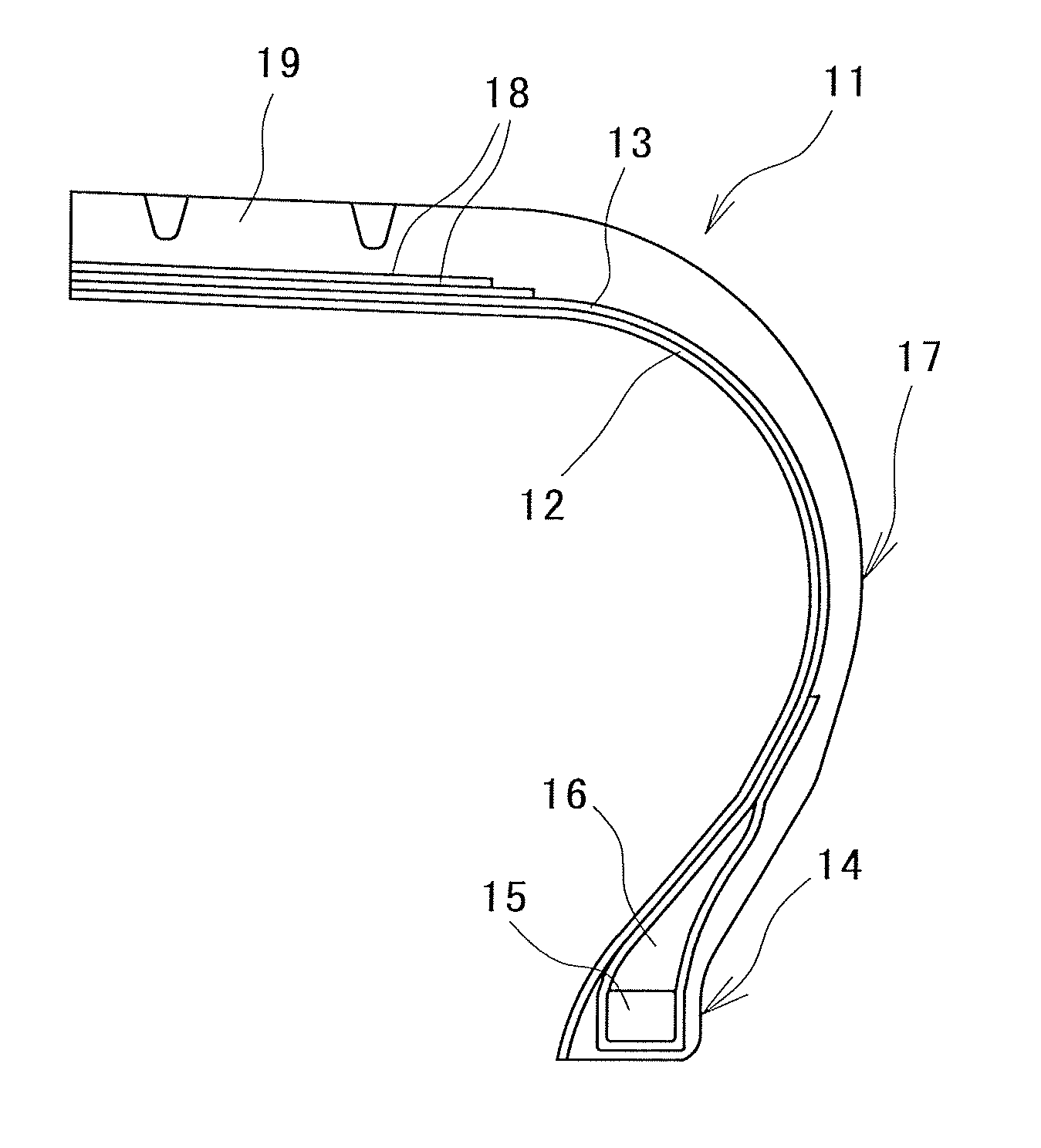
[0034]FIG. 10 exemplifies a pneumatic tire 11 produced according to the present invention. In the pneumatic tire 11, a carcass layer 13 is laid between a pair of bead portions 14. The carcass layer 13 is folded back around a bead core 15 from the inner side to the outer side, while sandwiching a bead filler 16. A film 12 is provided at the inner circumferential side of the carcass layer 13 as an inner layer to prevent air permeation. A rubber member forming a sidewall portion 17 and a rubber member forming a tread portion 19 are provided at the outer circumferential side of the carcass layer 13.

[0035]In the tread portion 19 at the outer circumferential side of the carcass layer 13, belt layers 18 are prov...


PUM

PropertyMeasurementUnit
thicknessaaaaaaaaaa
thicknessaaaaaaaaaa
temperatureaaaaaaaaaa

Abstract

A green tire (G) is formed by stacking a tire component such as a carcass layer (13) on a film (12) which is made of a thermoplastic resin or a thermoplastic elastomer composition and which is disposed on the entire outer circumferential surface of a cylindrical rigid inner die (1) formed of split parts (2). The green tire (G) is placed in a vulcanizing mold together with the rigid inner die (1) and then heated to a given temperature. The film (12) is pressurized from the inner circumferential side and inflated, and the green tire (G) is vulcanized. Thus, unvulcanized rubber of the tire components is pressed toward the inner circumferential surface of the vulcanizing mold and flows in circumferential directions. As a result, volume unevenness of the tire components is corrected. The film (12) which functions as a bladder is tightly bonded to the inner circumferential surface of the tire to become an inner layer of the tire.

Description

TECHNICAL FIELD[0001]The present invention relates to a process for producing a pneumatic tire. More specifically, the present invention relates to a process for producing a pneumatic tire capable of efficiently producing a pneumatic tire which includes a lightweight inner layer having excellent air permeation prevention performance and which is excellent in uniformity.BACKGROUND ART[0002]There have been proposed various processes for producing a pneumatic tire in which a green tire is formed on an outer circumferential surface of a rigid inner die made of metal, and in which the formed green tire is then placed inside a vulcanizing mold together with the rigid inner die and vulcanized (refer to Patent Documents 1 and 2, for example). According to the aforementioned production methods using the rigid inner die, a rubber-made bladder, which has been used heretofore, is no longer necessary. Thus, the step of removing the formed green tire from a making drum, or the like can be omitted...

Claims


Application Information

Patent Timeline
Patent Type & Authority Applications(United States)
IPC IPC(8): B29D30/16
CPCB29D30/0654B29D30/0661B29D2030/0682B29D30/10B29D2030/0655B29D30/0681
Inventor SANO, TAKUZOUTAKADA, NOBORU
Owner THE YOKOHAMA RUBBER CO LTD
Learn More