Camera device, and method and program for supporting focus adjustment

a technology for camera devices and focus adjustment, which is applied in the field of camera devices, can solve the problems of difficult to achieve accurate focus, take a lot of labor and trouble for installation, etc., and achieve the effect of easy adjustment of focus

Inactive Publication Date: 2010-12-30
PANASONIC CORP
View PDF6 Cites 2 Cited by
  • Summary
  • Abstract
  • Description
  • Claims
  • Application Information

AI Technical Summary

Benefits of technology

[0006]The present invention has been made under the circumstances described above. An object of the present invention is to provide a camera device capable of using a light emitter provided in the main body of the camera device to assist focus adjustment operation and allows one operator to easily adjust focus without the help of others.Means for Solving the Problems
[0011]According to yet another aspect of the present invention, there is provided a focus adjustment assisting program which causes a computer to execute the processes of determining a correct focus position representing a target position of focus adjustment on the basis of a parameter relating to a focus state calculated from a captured camera image, and controlling light emission of a light emitter provided in a main body of the apparatus to indicate the correct focus position to a user.
[0012]According to yet another aspect of the present invention, there is provided a focus adjustment assisting program which causes a computer to execute the processes of determining a correct focus position representing a target position of focus adjustment on the basis of a parameter relating to a focus state calculated from a captured camera image and, when a focus adjustment member is rotated relative to a base member during focus adjustment, controlling friction torque of the focus adjustment member applied to the base member so that a maximum friction torque is applied in the correct focus position.

Problems solved by technology

However, in conventional focus adjustment methods, it is not easy to achieve accurate focus and it takes a lot of labor and trouble for the installation since two operators perform focus adjustment in cooperation.

Method used


Image

  • Camera device, and method and program for supporting focus adjustment
  • Camera device, and method and program for supporting focus adjustment
  • Camera device, and method and program for supporting focus adjustment

Examples


first embodiment

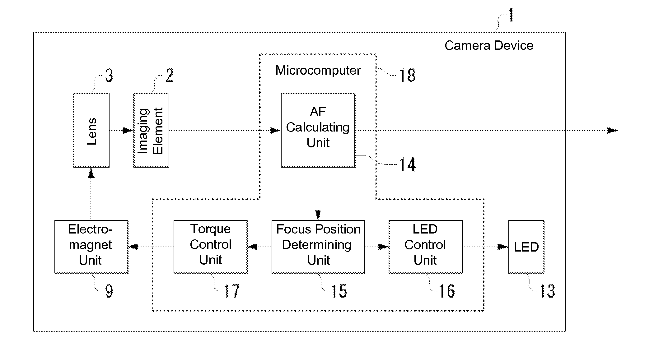
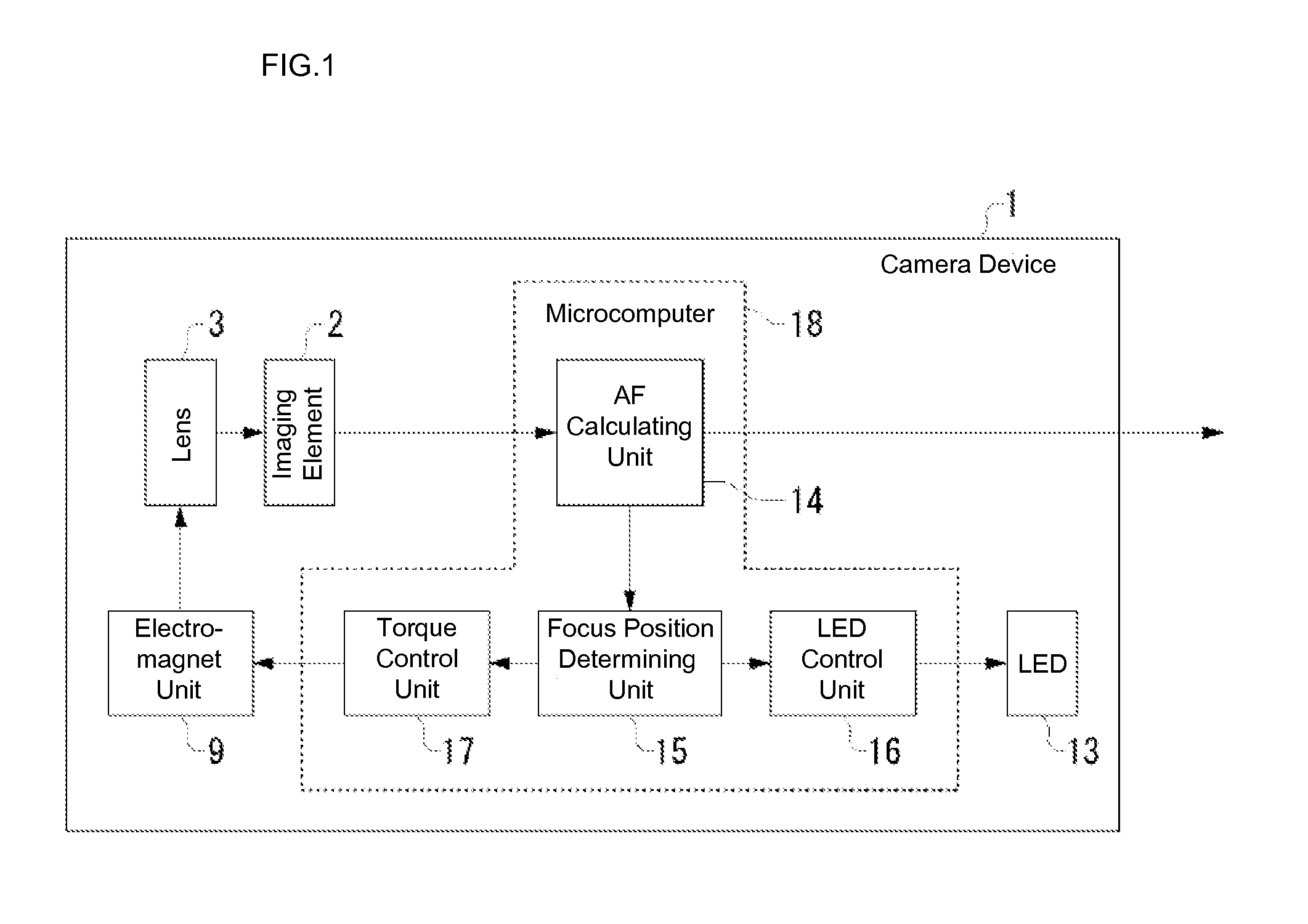
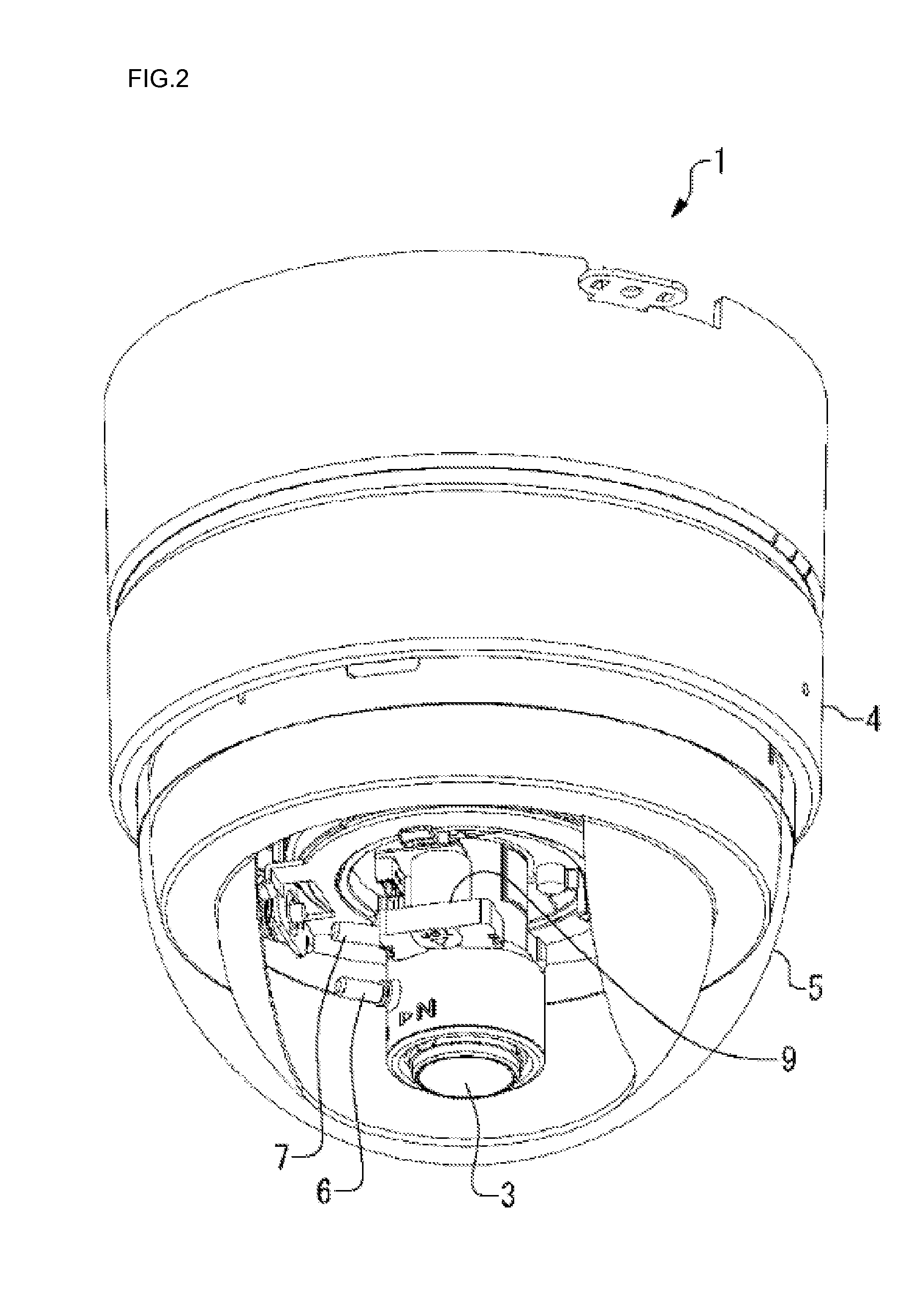
[0059]A configuration of a camera device according to a first embodiment of the present invention will be described with reference to FIGS. 1 to 5. FIG. 1 is a block diagram illustrating a configuration of a camera device according to the present embodiment. FIG. 2 is a perspective view of the camera device, FIG. 3 is a perspective view of the camera device with a dome cover removed, FIG. 4 is a side view of the camera device with the dome cover removed, and FIG. 5 is a plan view of the camera device with the dome cover removed.

[0060]As illustrated in FIGS. 1 to 5, the camera device 1 includes a main body 4 including an image imaging element 2 and a lens 3 for capturing a camera image and a dome cover 5 for protecting the image imaging element 2 and the lens 3. The image imaging element 2 is a solid-state image imaging element such as a CCD or a CMOS device. The lens 3 is a varifocal lens, for example.

[0061]The varifocal lens 3 has a focus lock knob 6 used for manual focus adjustmen...

second embodiment

[0087]A camera device 1 according to a second embodiment of the present invention will be described with reference to FIG. 9. The following description will focus on differences of the camera device 1 of the second embodiment from that of the first embodiment. The configuration and operations of the camera device 1 of the second embodiment are the same as those in the first embodiment unless otherwise stated.

[0088]A configuration of the camera device 1 according to the second embodiment will be described first. The camera device 1 of the present embodiment differs from that of the first embodiment in that the camera device 1 of the second embodiment includes two LEDs for indicating a correct focus position to a user. As illustrated in FIG. 9, two LEDs 20 and 21 are provided on the NEAR and FAR sides, respectively, in the present embodiment. The two LEDs 20 and 21 in the present embodiment are dedicated to indication of a correct focus position. However, the LEDs 20 and 21 may also b...


PUM


Abstract

A camera device (1) comprises an AF value calculating unit (14), a focus position determining unit (15), and an LED control unit (16). The AF value calculating unit (14) calculates an AF value from a camera image captured by an image imaging element (2). The focus position determining unit (15) determines a correct focus position based on the AF value. The LED control unit (16) controls light emission of an LED (13) provided in a main body (4) and indicates the correct focus position to a user. This allows to assist the user in focus adjustment by means of a light emitter provided in the main body. Thus, the camera device which allows the user by himself to adjust focus with ease without the help of others is provided.

Description

TECHNICAL FIELD[0001]The present invention relates to a camera device including the function of using a light emitter provided in the main body of the camera device to assist focus adjustment operation.BACKGROUND ART[0002]Surveillance cameras installed on ceilings and walls of facilities and buildings that use a varifocal lens have been known. A varifocal lens is a simplified version of a zoom lens and involves focus adjustment when zooming is performed. Focus adjustment of the varifocal lens can be accomplished by manually rotating a focus ring provided on a lens barrel. Such a mechanism is disclosed in Japanese Patent Laid-Open No. 5-323422 (pp. 3-4, FIG. 1), for example.[0003]For a surveillance camera that uses such a varifocal lens, a monitor that outputs camera images are often provided in a location (for example in a surveillance monitor room) remote from the location where the surveillance camera is installed. In such a case, installation of the surveillance camera is perform...

Claims


Application Information

Patent Timeline
Patent Type & Authority Applications(United States)
IPC IPC(8): H04N5/232
CPCG02B7/36H04N5/23212G03B17/18G02B7/38H04N23/673H04N23/675H04N23/55
Inventor MORI, YUUICHIROUMIZUNO, MASAFUMINAKAMURA, YASUJIHATTA, SHOJI
Owner PANASONIC CORP
Why Eureka
Try Eureka