Laser marking machine provided with light focusing groove

A technology of laser marking machine and light groove, which is applied in the field of laser marking machines, can solve the problems of invisible focus, difficult determination, and workpiece loss, etc., so as to facilitate the work of adjusting the focal length, reduce laser deviation, and improve production efficiency effect

Inactive Publication Date: 2018-02-16
张家港市旭华激光有限公司
View PDF6 Cites 1 Cited by
  • Summary
  • Abstract
  • Description
  • Claims
  • Application Information

AI Technical Summary

Problems solved by technology

[0003] In the laser marking work, after the laser generates laser light and passes through a set of optical systems, the laser beam passes through the marking head, and the laser marking head guides the laser beam to pass through the focusing lens to converge into a small light spot and mark on the surface of the object. However, the laser marking head must always maintain a fixed distance from the surface of the object, the focal length, the focal length of each is determined by the focusing lens, and the beam will converge into a small light spot after passing through the focusing lens. As the focus, the workpiece to be processed is placed on the focus to achieve the best marking effect. In actual work, the laser is invisible, and the focus is invisible and intangible. It is not easy to determine. The existing focus positioning uses direct marking. It is cumbersome to determine with a ruler, and after the focus lens of the same marking machine is replaced, the focus needs to be readjusted, and the focal length error may cause the loss of the workpiece. Since the laser uses invisible light, it is more common to operate the laser without work experience. At the same time, the materials and structural shapes of the materials to be processed are not exactly the same, so the focus can be quickly positioned, which can improve work efficiency and save working time

Method used


Image

  • Laser marking machine provided with light focusing groove

Examples


Embodiment Construction

[0015] The preferred embodiments of the present invention will be described in detail below in conjunction with the accompanying drawings, so that the advantages and features of the present invention can be more easily understood by those skilled in the art, so as to define the protection scope of the present invention more clearly.

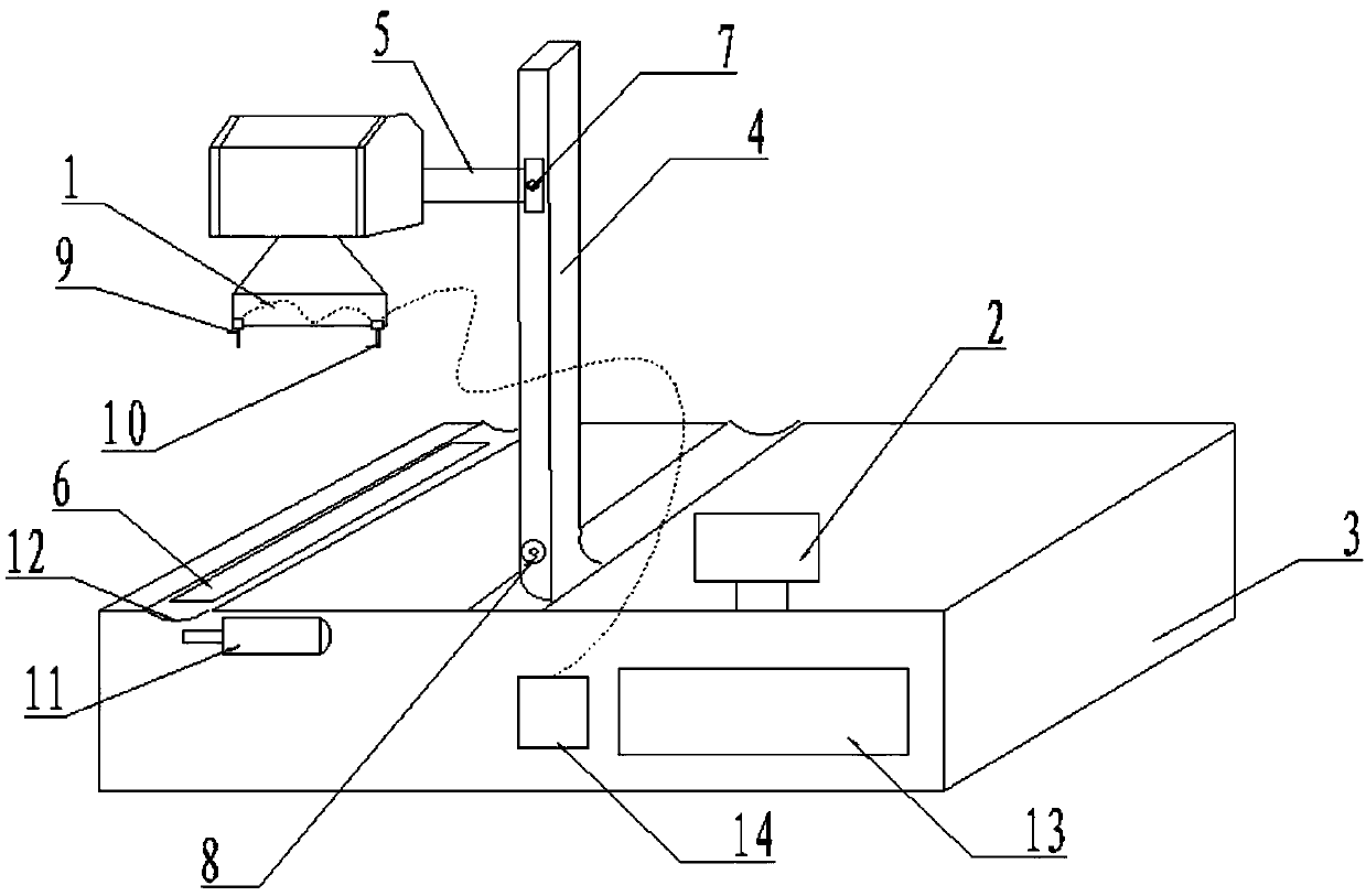
[0016] see figure 1 , the embodiment of the present invention includes:

[0017] The laser marking machine with an alignment groove includes: a base, the base adopts a cuboid structure, and friction stripes are set at the lower end of the base to increase the firmness of the base, and a support is set on the base Column, the support column adopts a cuboid structure, the adjustment axis A is set on the support column, the support column is connected with the laser cross arm through the adjustment axis A, the laser is set on the laser cross arm, the upper end of the laser is equipped with a shading cover, and the lower end of the laser is set Two ...


PUM


Abstract

The invention discloses a laser marking machine provided with a light focusing groove. The laser marking machine comprises a base, a supporting column is arranged on the base, an adjusting shaft A isarranged on the supporting column, and the supporting column is connected with a laser cross beam through the adjusting shaft A. A laser is arranged on the laser cross beam, the laser comprises a laser generator, a light condensation cavity is connected to the front end of the laser generator, and the rear end of the laser generator is a total reflection mirror. An adjusting shaft B is arranged onthe supporting column, a workpiece groove is formed in the base, a guide rail is arranged on the workpiece groove, and the adjusting shaft B can adjust the relative positions of a workpiece and a laser beam. The laser marking machine provided with the light focusing groove can facilitate work of focal length adjusting of laser, and laser deviation caused by inaccuracy of manual laser focal lengthadjusting is reduced.

Description

technical field [0001] The invention relates to the technical field of laser equipment, in particular to a laser marking machine with an alignment groove. Background technique [0002] Laser equipment is more and more widely used in modern society. It is mainly used for laser cutting, laser welding, laser drilling, and laser marking. The laser beam is used to interact with the workpiece to be worked, and the surface of the workpiece is subjected to high-temperature heat treatment to complete industrial applications. [0003] In the laser marking work, after the laser generates laser light and passes through a set of optical systems, the laser beam passes through the marking head, and the laser marking head guides the laser beam to pass through the focusing lens to converge into a small light spot and mark on the surface of the object. However, the laser marking head must always maintain a fixed distance from the surface of the object, the focal length, the focal length of e...

Claims


Application Information

Patent Timeline
IPC IPC(8): B23K26/362B23K26/08
CPCB23K26/08B23K26/361
Inventor 孟燕
Owner 张家港市旭华激光有限公司
Why Eureka
Try Eureka