
Hot water supply system for constantly maintaining temperature of hot water

a hot water supply system and constant temperature technology, applied in the field of hot water supply systems for maintaining a constant temperature of hot water, can solve the problems of reducing the heating power of the burner, reducing so as to achieve the effect of maximizing the efficiency of the water heater and enhancing the overshoot and the undershoo

Active Publication Date: 2010-12-30
KYUNGDONG NAVIEN
View PDF14 Cites 23 Cited by
  • Summary
  • Abstract
  • Description
  • Claims
  • Application Information

AI Technical Summary

Benefits of technology

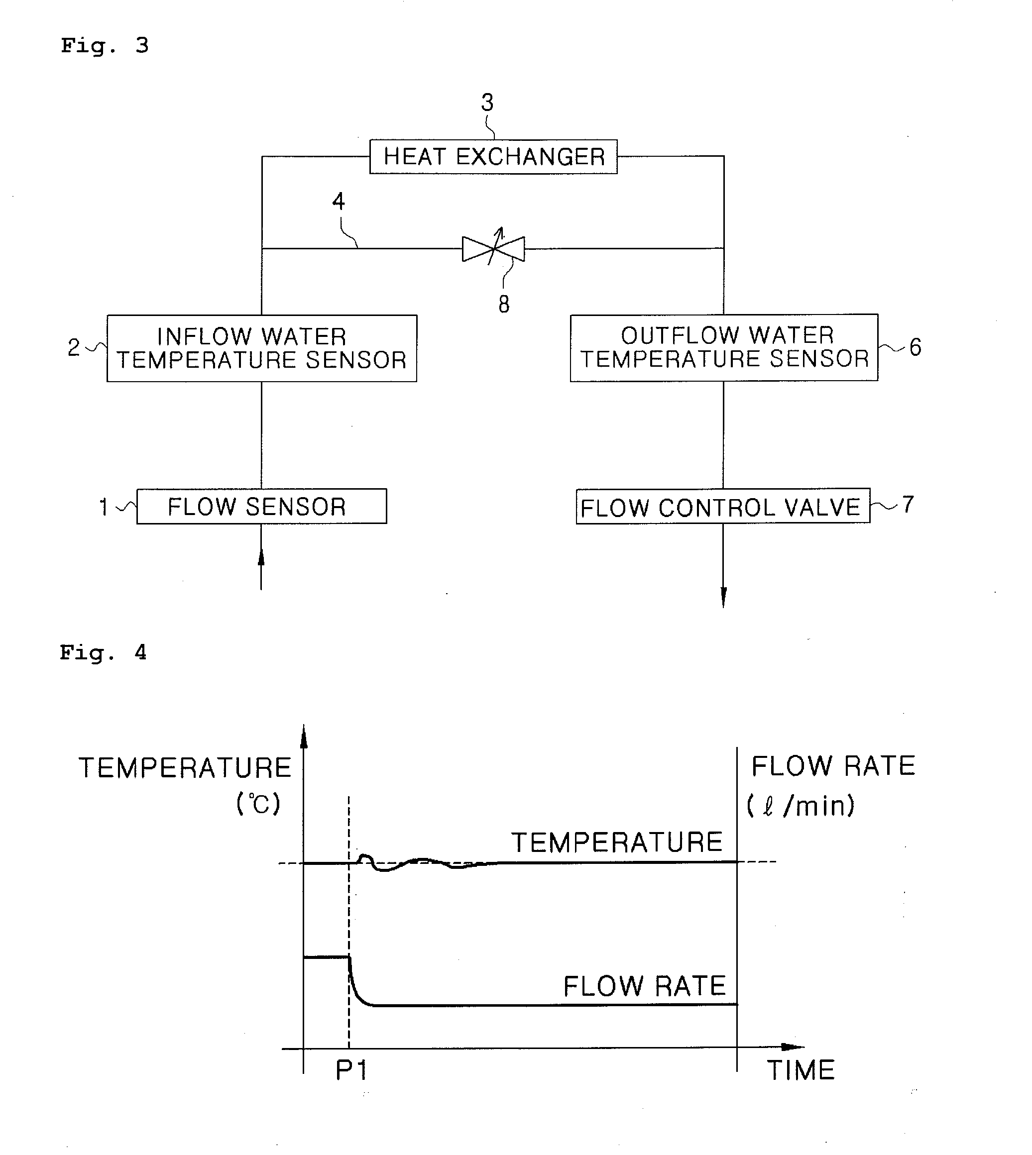
[0019]Accordingly, it is a first object of the present invention to provide a hot water supply system for maintaining a constant temperature of hot water that enhances an overshoot and a undershoot of the temperature of the hot water, which temporarily occur depending on variation in the usage of the hot water while maximally maintaining efficiency of a water heater.
[0020]Further, it is a second object of the present invention to provide a hot water supply system for maintaining a constant temperature of hot water that recovers condensed heat of exhaust gas to improve efficiency of a water heater by controlling a temperature at an outlet of a heat exchanger to be a condensing temperature of the exhaust gas or less in the case of a condensing water heater.
[0021]In addition, it is a third object of the present invention to provide a hot water supply system for maintaining a constant temperature of hot water that prevents lime from being extracted in a heat exchanger by controlling an internal temperature of the heat exchanger to be a lime extraction temperature or less, when inflow water contains lime components.
[0028]According to the present invention, when the usage of the hot water is changed, a temporary change of the temperature of the hot water can be absorbed from a water tank, such that the hot water can be used without a rapid change in the temperature of the hot water. Further, in the case of a condensing water heater, as an outlet temperature of the heat exchanger is controlled to be a condensing temperature of exhaust gas or less, efficiency of the water heater is increased and an internal temperature of the heat exchanger can be controlled to be a temperature lower than a temperature at which lime is extracted, such that it is possible to prevent durability of the heat exchanger from being deteriorated.

Problems solved by technology

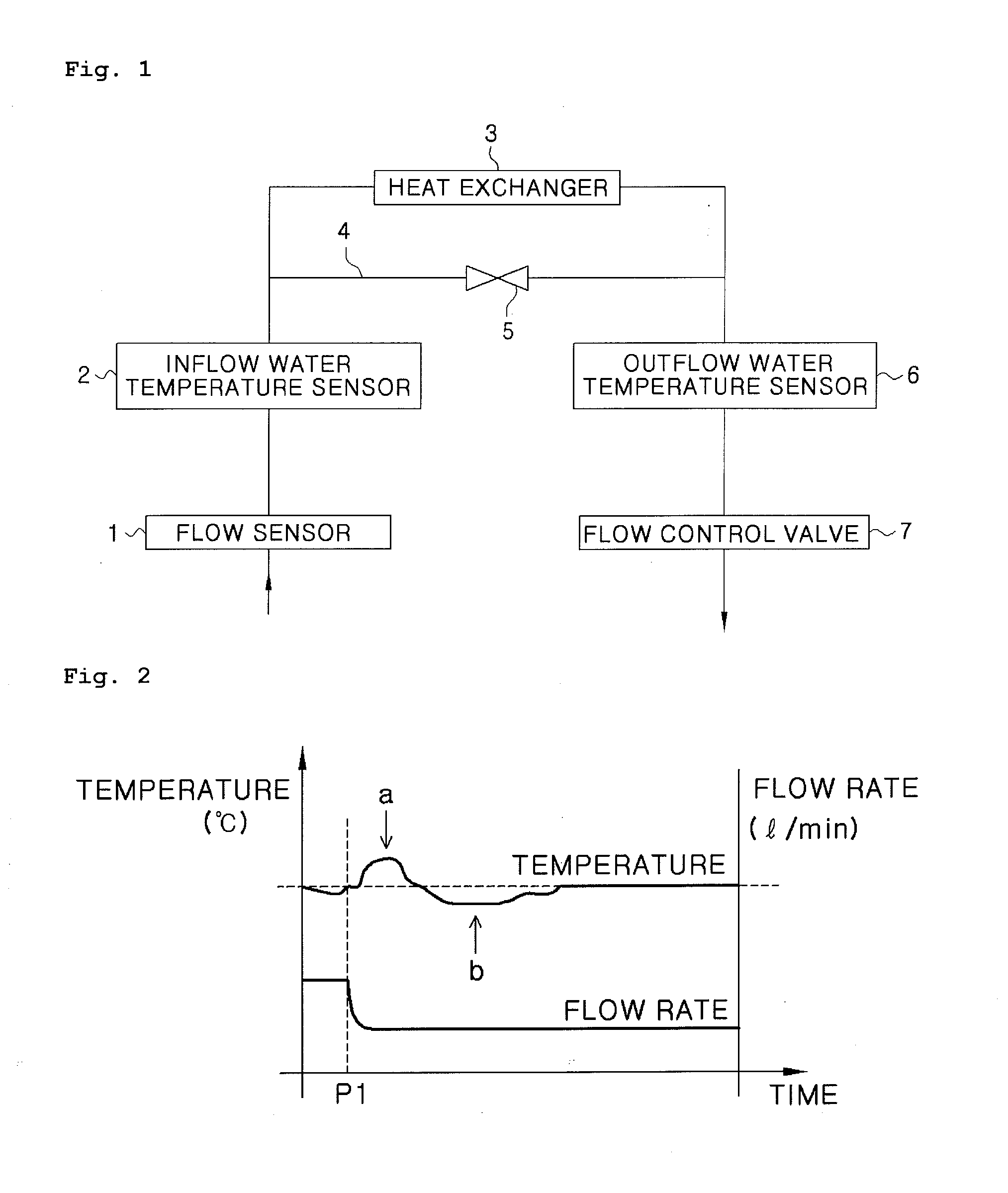
As a result, in this state, even though the flow rate passing through the heat exchanger is decreased to thereby reduce the heating power of the burner, hot water having a temperature higher than a set temperature temporarily flows out.
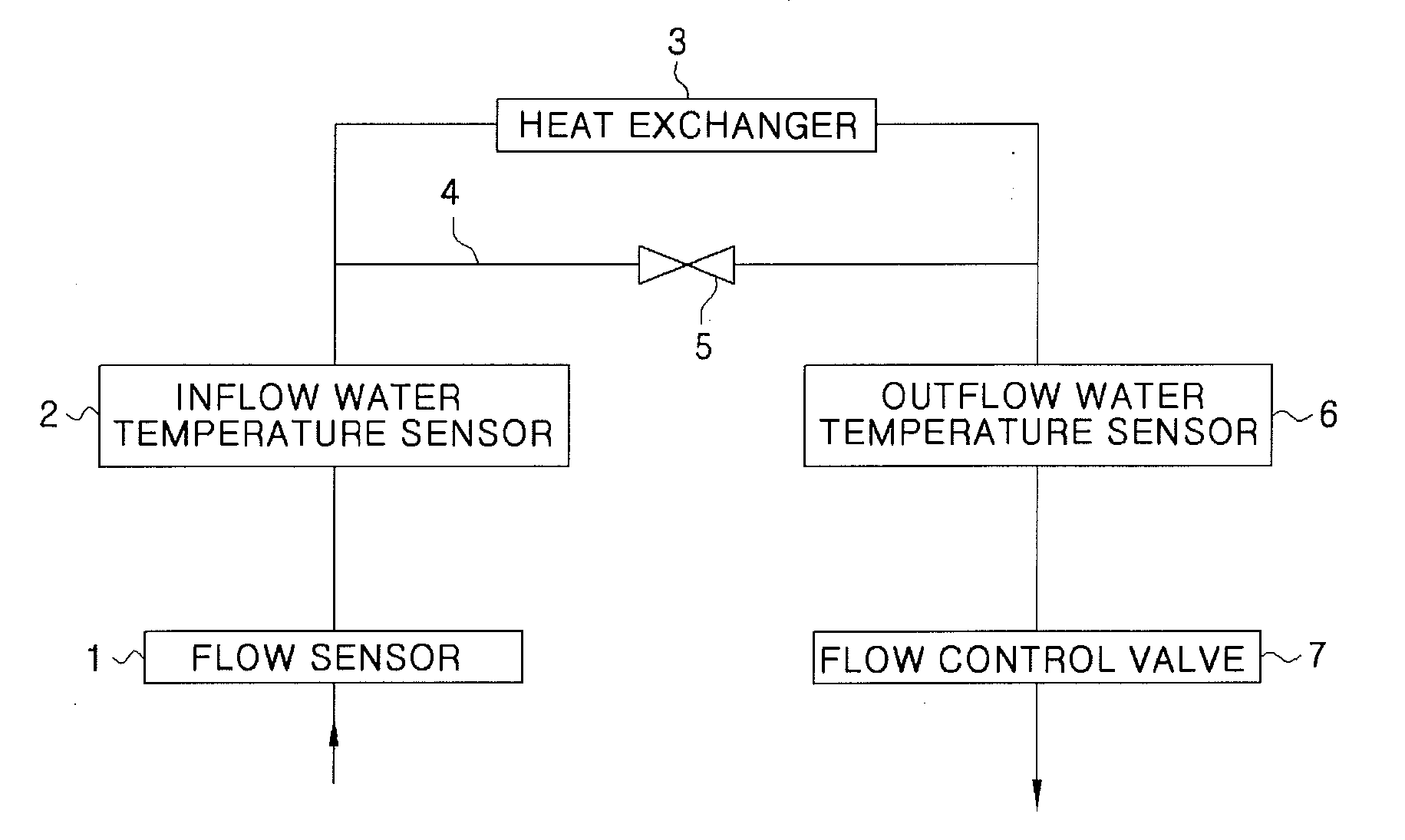
However, in the case when the user uses the large flow rate of hot water from the small flow rate of hot water, the water heater having the by-pass valve 5 is difficult to prevent the undershoot from being increased.
As described above, the water heater shown in FIG. 1 can enhance the temporary overshoot of the temperature of the hot water which occurs due to the decrease of the usage of the hot water, while the water heater is unable to effectively deal with the undershoot when the usage of the hot water is increased.
However, the water heater has a problem in that a temperature at an outlet of the heat exchanger is controlled to be higher than the user set temperature by approximately 20° C. on the average in order to improve controlling the temperature of the hot water depending on the variation of the flow rate when the hot water is used, such that efficiency of the water heater is decreased.
In this case, when the outlet temperature of the heat exchanger is controlled to be high, the hot water outlet temperature is higher than a condensing temperature of the exhaust gas which is approximately 55° C. or less, such that it is difficult that the exhaust gas is condensed.
Therefore, the condensed heat of the exhaust gas cannot be recovered to thereby decrease the efficiency of the water heater.
When water which flows into the user's inflow pipe contains the lime, the lime is extracted in the heat exchanger, such that the efficiency of the water heater is deteriorated after use over a long period and heat transmission is decreased in the heat exchanger, such that partial boiling may occur to thereby deteriorate durability of the water heater.

Method used


Image

  • Hot water supply system for constantly maintaining temperature of hot water
  • Hot water supply system for constantly maintaining temperature of hot water
  • Hot water supply system for constantly maintaining temperature of hot water

Examples


first embodiment

[0044]FIG. 5 is a diagram illustrating a configuration of a water heater according to the present invention. FIG. 6 is a diagram illustrating a flow path of water while preheating. FIG. 7 is a diagram illustrating a flow path of water while using hot water.

[0045]As shown in FIG. 5, the water heater 100 according to the first embodiment of the present invention includes an inflow water temperature sensor 11 that measures a temperature of water that flows into an inlet 10, a flow sensor 12 that measures flow rate of the inflow water, a heat exchanger 13 that transmits, heat of a burner to the inflow water so as to send the inflow water having a user set temperature, an outflow water temperature sensor 14 that measures a temperature of water that flows out from the heat exchanger, a water tank 15 that stores the water that flows out from the heat exchanger 13, a flow control valve 16 that controls flow rate of hot water, a pump 17 that is installed on a pipe 24 for connecting a first d...

second embodiment

[0063]Hereinafter, referring to FIGS. 8 to 10, a water heater 100 according to the present invention will be described.

[0064]FIG. 8 is a diagram illustrating a configuration of a water heater 100 according to a second embodiment of the present invention. FIG. 9 is a diagram illustrating a flow path of water while preheating. FIG. 10 is a diagram illustrating a flow path of water in using hot water.

[0065]As shown in FIG. 8, the water heater 100 according to the second embodiment of the present invention includes a 3-way valve 19 installed on the pipe 24 for connecting the first diverging point 21 and the second diverging point 22 in addition to the components of the water heater 100 according to the first embodiment of the present invention. Further, a third diverging point 23 is formed on a pipe for connecting the first diverging point 21 and the outlet 20 and a radiator 25 is provided on an additional pipe for connecting the third diverging point 23 and the 3-way valve 19. The 3-wa...


PUM


Abstract

The present invention relates to a hot water supply system that heats low-temperature water flowing into an inlet at a high temperature by using a heating device and supplies the high-temperature water through an outlet. The hot water supply system according to the present invention includes a heat exchanger that transmits heat of the heating device to the inflow water so as to supply the inflow water at a user set temperature; a flow sensor that measures a flow rate of the water flowing into the hot water supply system; a water tank that stores water discharged from the heat exchanger, a temperature sensor that is installed at a predetermined position on a pipe through which the water flows; and a controller that has an input unit to allow a user to input desired conditions, wherein the controller controls the operation of the heating device by comparing the user set temperature with a temperature measured by the temperature sensor and controls the operation of the heating device depending on variation in the flow rate measured by the flow sensor.

Description

BACKGROUND OF THE INVENTION[0001]1. Field of the Invention[0002]The present invention relates to a hot water supply system for maintaining a constant temperature of hot water, and more particularly, to a hot water supply system for maintaining a constant temperature of hot water that enhances an overshoot and a undershoot of the temperature of the hot water, which temporarily occur depending on variation of usage of the hot water.[0003]2. Description of the Related Art[0004]In general, a hot water supply system (hereinafter, referred to as “water heater”) is used for heating and supplying water at a predetermined temperature within a short time. A performance of the water heater is primarily determined depending on how rapidly a temperature of hot water reaches a user setting temperature and whether hot water maintaining the user setting temperature can be supplied even if usage of the hot water varies.[0005]FIG. 1 is a diagram illustrating a configuration of a known water heater ha...

Claims


Application Information

Patent Timeline
Patent Type & Authority Applications(United States)
IPC IPC(8): F24H1/18H05B1/02
CPCF24D17/0031F24D19/1012F24D19/1015Y02B30/745F24D2220/044F24D2220/08G05D23/192F24D2220/042Y02B30/70F24H15/174F24H15/215F24H15/32F24H15/238F24H15/219F24H15/281F24H15/172F24D19/1009F24H15/136F24H15/36
Inventor KIM, YONG-BUMKIM, SI-HWAN
Owner KYUNGDONG NAVIEN
Learn More