
Improved portable restroom structure, component parts and method of

a portable restroom and component technology, applied in the field of portable restroom structures, can solve the problems of more installation costs and cumbersome systems, and achieve the effect of quick and easy removal, quick and easy change, and convenient replacemen

Inactive Publication Date: 2011-01-06
GEBRKA THOMAS
View PDF2 Cites 30 Cited by
  • Summary
  • Abstract
  • Description
  • Claims
  • Application Information

AI Technical Summary

Benefits of technology

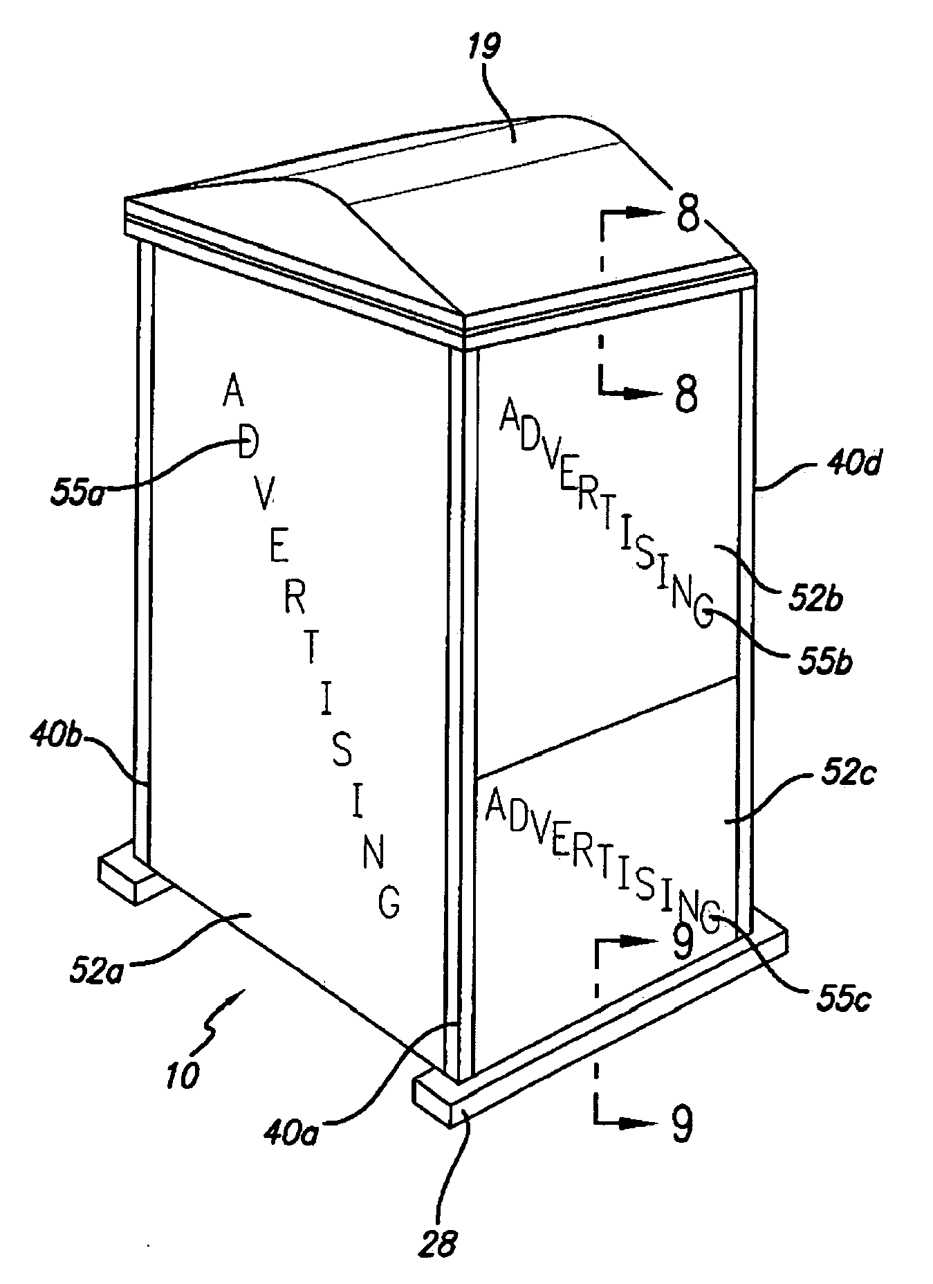
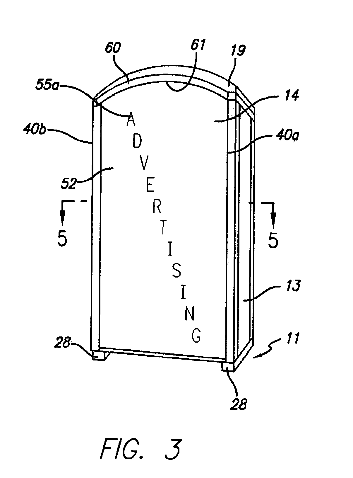
[0005]In another aspect of the invention, a portable shelter having an integral mount for detachably displaying an advertising panel is provided. Preferably, a improved corner piece for constructing the portable shelter is utilized which includes a body portion having a pair of wall panel notches for receipt of a vertical wall panel forming the shelter, and at least one advertising panel notch for receipt of at least one advertising panel to assist in mounting the advertising panel to shelter. Such corner pieces are preferably utilized on at least the two back corners of such a shelter, but may be utilized on four or more corners of the structure. The corner pieces of the invention are preferably adapted for use with vertical wall panel sections which are substantially planar except along their vertical edges where snap fit structures are provided. The corner piece of the invention preferably is an elongated structure which extends vertically from the base of the shelter to roof line. The horizontal length of the advertising panel notch is preferably shallow enough that the vertical edges of the flexible and resilient advertising panel can be flexed along its vertical axis such that its vertical edges are temporarily and resiliently displaced horizontally inwardly so they can be easily dismounted from the shelter.
[0010]In accordance with another aspect of the invention, a method is provided for the temporary display of advertising material by which temporary advertising materials may be quickly and easily removed from the exterior surface of a portable shelter including the steps of providing a portable building having at least two corner pieces with each of the corner pieces defining at least a portion of an integral vertical advertising panel slot and with the adjacent advertising panel slots being coplanar and spaced apart a predetermined distance; providing a resilient advertising panel having vertical edges spaced apart by a distance slightly greater than the predetermined distance when the advertising panel is held in a substantially planar conformation and slightly less than the predetermined distance when temporarily and resiliently flexed along its vertical axis; flexing the advertising panel along its vertical axis sufficiently to cause a least one vertical edge of the advertising panel to be temporarily and resiliently displaced horizontally inwardly; inserting at least one vertical edge of the flexed advertising panel into at least one of the advertising panel slots; displaying the advertising indicia on the exterior surface of the advertising panel; and removing the advertising panel by flexing the advertising panel along its vertical axis enough to cause at least one of the edges of the advertising panel to be displaced sufficiently inwardly to release it from the advertising panel slot; and once the first advertising panel edge is released from the advertising panel slot, removing the other edge of the advertising panel from the advertising panel slot.
[0011]In accordance with still another aspect of the invention, a method of quickly and easily changing an advertising message mounted on the exterior surface of a portable shelter is provided, including the steps of providing a portable building having adjacent corner pieces with each of the corner pieces defining at least a portion of an integral vertical advertising panel slot and with the adjacent advertising panel slots being coplanar and spaced apart a predetermined distance; providing a resilient first advertising panel with a first advertising message thereon and having vertical edges spaced apart by a distance slightly greater than the predetermined distance when the first advertising panel is held in a substantially planar conformation and slightly less than the predetermined distance when temporarily and resiliently flexed along its vertical axis; flexing the first advertising panel along its vertical axis sufficiently to cause a least one vertical edge of the first advertising panel to be temporarily and resiliently displaced horizontally inwardly; inserting at least one vertical edge of the flexed first advertising panel into at least one of the advertising panel slots, displaying the first advertising message on the exterior surface of the first advertising panel; removing the first advertising panel by flexing the first advertising panel along its vertical axis enough to cause at least one of the edges of the first advertising panel to be displaced sufficiently inwardly to release it from the advertising panel slot; upon released of one of the edges of the first advertising panel from the advertising panel slot, removing the other edge of the panel from the advertising panel slot; providing a second resilient advertising panel with a different advertising message than the first advertising message of the first advertising panel; the second advertising panel having vertical edges spaced apart by a distance slightly greater than the predetermined distance when the second advertising panel is held in a substantially planar conformation and slightly less than the predetermined distance when temporarily and resiliently flexed along its vertical axis; inserting the at least one vertical edge of the flexed second advertising panel into at least one of the advertising panel slots, displaying the advertising message on the exterior surface of the second advertising panel.

Problems solved by technology

That system is more cumbersome and involves more expense to install the temporary advertising than the present inventor believes to be desirable.

Method used


Image

  • Improved portable restroom structure, component parts and method of
  • Improved portable restroom structure, component parts and method of
  • Improved portable restroom structure, component parts and method of

Examples


Embodiment Construction

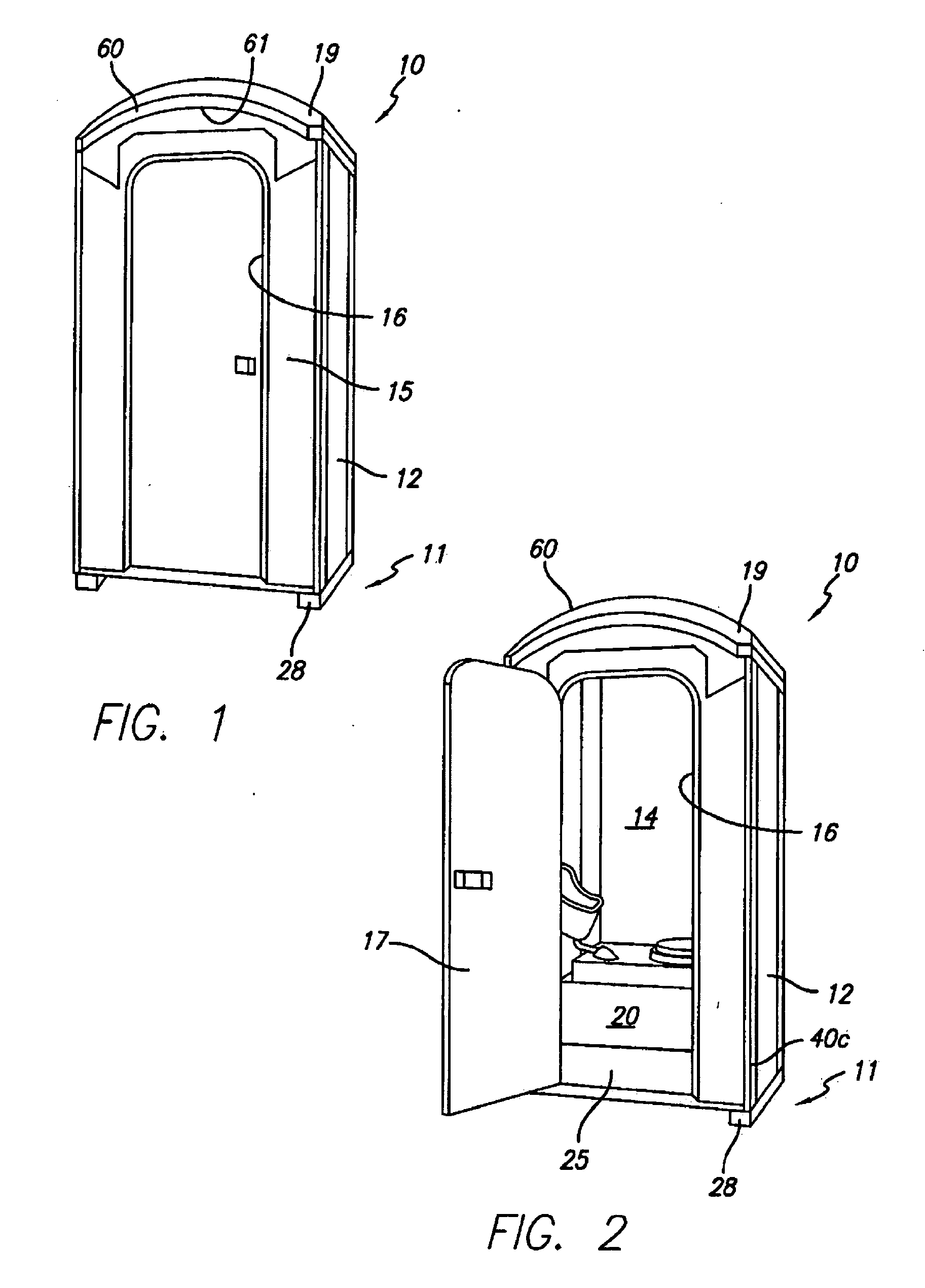
[0024]Referring to FIGS. 1-3, a portable restroom 10 is illustrated which is formed of a number of separate structural components. The restroom structure has a base 11, formed as a support pallet to which vertical wall panels 12-15 are connected. The wall panels include two side wall panels 12-13, a rear wall panel 14 and a front wall panel 15. The side and rear wall panels are substantially identical in construction in order to simplify the manufacture of the product, although they may be designed to be somewhat different if so desired. The front wall panel 15 has a doorway opening 16 which is covered by a hinged door 17. The door is connected by hinges 18 (FIG. 4) to the vertical side edge defining the doorway opening. A roof 19 covers the opening formed by the enclosure defined by the wall panels 12-15. A toilet waste tank 20 is positioned near the base of the enclosure.

[0025]As best seen in FIG. 4, the base 11 is provided with a floor panel 25 secured upon a frame 26. The floor ...


PUM


Abstract

A small shelter having an integral mount for detachably displaying an advertising panel having predetermined dimensions is provided. The small shelter includes a plurality of vertical wall panels joined together to define an interior portion of the small shelter. At least one of the plurality of vertical wall panels has an inner surface defining at least a portion of the interior space of the shelter and an outer surface defining at least a portion of the exterior surface of the shelter. The exterior surface of the shelter includes at least two integral, co-planar, advertising panel slots, which extend along opposing vertical margins of a portion of the shelter. Each of the advertising panel slots is adapted to retain a vertical edge of the advertising panel to detachably mount the first advertising panel to the exterior surface of the shelter.

Description

[0001]This application is a continuation-in-part of U.S. Patent Application Ser. No. 61 / 032,023 filed on Feb. 27, 2008. The present invention is directed to small shelters frequently utilized as portable restrooms and component parts for use in the manufacture of such shelters. More particularly, the invention is directed to a novel integral mounting structure for detachably mounting advertising materials on the exterior of such shelters as well as to improved methods of mounting and removal of such advertising materials.FIELD OF THE INVENTIONBackground of the Invention[0002]There are currently a variety of structures for adapting portable restrooms to serve as a display for advertising materials. One such system is described in U.S. Pat. No. 6,763,626 issued to Wiering a. The system of the '626 patent involves the installation of a multiple, large metallic clamps using hand and power tools on a series of adjacent portable restrooms. That system is more cumbersome and involves more ...

Claims


Application Information

Patent Timeline
Patent Type & Authority Applications(United States)
IPC IPC(8): E03D1/00G09F7/08
CPCG09F15/00E04H1/1216G09F15/0012G09F15/0043G09F23/00
Inventor GEBKA, THOMAS
Owner GEBRKA THOMAS
Learn More