Mechanical self destruct for runaway escapements

a self-destructing and escapement technology, applied in the field of self-destructing escapement mechanisms for munitions, can solve problems such as significant problems in conventional runaway escapements

Active Publication Date: 2011-01-06
AMTEC CORP
View PDF31 Cites 0 Cited by
  • Summary
  • Abstract
  • Description
  • Claims
  • Application Information

AI Technical Summary

Benefits of technology

[0020]Another important object is to provide a self-destruct mechanism that is activated when centrifugal forces acting on the mechanism fall below a preselected threshold, thereby avoiding false activations that may be caused by electrical components.

Problems solved by technology

However, a significant problem exists in conventional runaway escapements.

Method used


Image

  • Mechanical self destruct for runaway escapements
  • Mechanical self destruct for runaway escapements
  • Mechanical self destruct for runaway escapements

Examples


Embodiment Construction

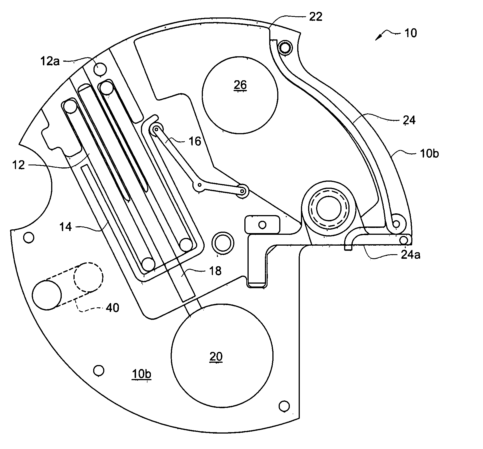
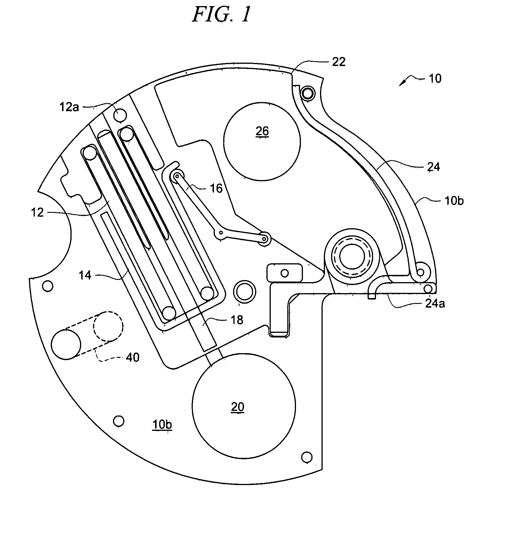
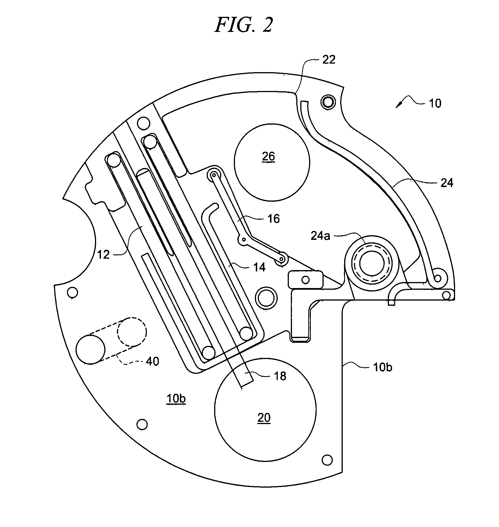
[0028]The novel method includes the steps of striking the side of a stab detonator in a runaway escapement with a firing pin. The firing pin is displaced when a bias member such as a spring under compression is released when the RPM of the round becomes less than that at full range. The warhead goes high order if the rotor is in the armed position. The warhead does not go high order if the rotor is in any position other than its fully armed position.

[0029]If the rotor is in any position other than armed, the detonator is fired and hence the round is classified as safe. This is because the rotor, when in any position other than fully armed, prevents the detonator from aligning with a spit back in projectiles having spit backs, and prevents the detonator from aligning with the primary charge / warhead in those projectiles lacking spit backs. If a detonator detonates when it is misaligned with a spit back or misaligned with a primary charge, the primary charge cannot explode. However, af...


PUM


Abstract

An escapement fuze self-destruct mechanism for a projectile includes a drive weight that maintains a biasing member in a compressed state by centrifugal force when a projectile's RPM speed is above a preselected threshold. When the RPM speed falls below the preselected threshold, the biasing member exerts sufficient counter-rotational force to overcome the centrifugal force exerted by the drive weight. The biasing member expands to an uncompressed state and displaces the drive weight into position for mechanically implementing self-destruction of the projectile if a rotor is fully armed or for rendering the projectile “safe” if the rotor is in any position other then fully armed.

Description

FIELD OF INVENTION[0001]This invention relates to self destruct mechanisms for munitions. More particularly, it relates to a self destruct mechanism for runaway escapements.BACKGROUND OF THE INVENTION[0002]When conventional ammunition is fired, pressure is generated by a propellant that burns in a high-pressure chamber. The pressure forces expanding gases to flow through vent holes into a low-pressure chamber and propels a projectile from the high-pressure chamber. A rotating band around the projectile engages rifling in a launcher tube thereby generating a high RPM spin to the projectile. Upon firing, setback force causes the fuze setback pin to move away from the fuze rotor. The rotor is held out of line with a fuze detonator by the setback pin and a fuze centrifugal lock that engages gear teeth of the fuze rotor.[0003]When the projectile attains sufficient spin, the centrifugal lock releases the rotor and arming begins. The rotor begins rotation toward the center of the projectil...

Claims


Application Information

Patent Timeline
Patent Type & Authority Applications(United States)
IPC IPC(8): F42C15/26
CPCF42C15/44F42C15/26F42C15/188F42C9/18F42C9/14
Inventor TAYLOR, NORMAN C.
Owner AMTEC CORP
Why Eureka
Try Eureka