Variable valve timing device

a timing device and variable valve technology, applied in valve arrangements, machines/engines, mechanical equipment, etc., can solve problems such as the failure of the lock pin by sticking in the bore, and achieve the effect of restricting the relative rotation range of the rotor

Inactive Publication Date: 2011-01-06
DENSO CORP
View PDF5 Cites 9 Cited by
  • Summary
  • Abstract
  • Description
  • Claims
  • Application Information

AI Technical Summary

Benefits of technology

[0009]It is an object of the present invention to provide a VVT which is capable of determining stuck failure of a movable restricting member for restricting relative rotational range of rotors.
[0010]It is another object of the present invention to provide a VVT which is capable of determining stuck failure of a pin for locking rotors.

Problems solved by technology

However, since the lock pin is moved between the projected position and the retracted position, the lock pin may be failed by sticking in a bore, such as in a projected stuck failure and a retracted stuck failure.
Further, the stuck determination unit determines that a restriction member is stuck in an abnormal state when the restricting condition or the enabling condition is satisfied and a restriction mechanism does not provide a restricted state or an enabled state corresponding to the satisfied condition.

Method used


Image

  • Variable valve timing device
  • Variable valve timing device
  • Variable valve timing device

Examples


first embodiment

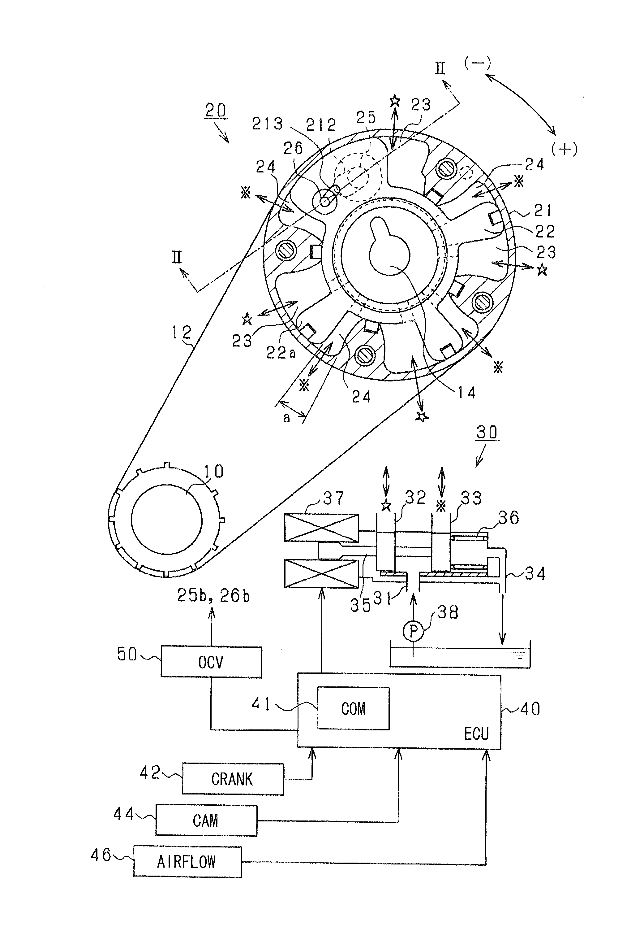
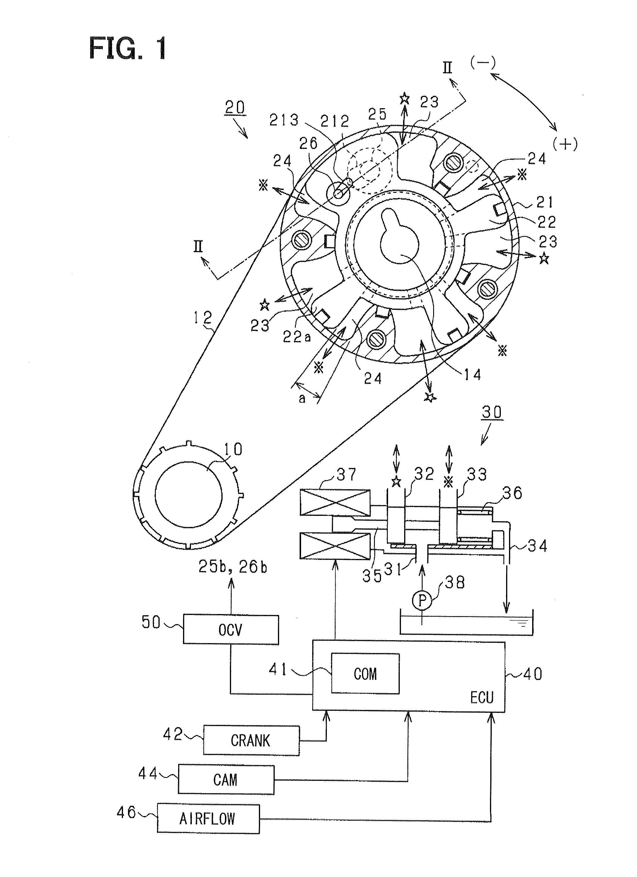
[0038]FIG. 1 is a block diagram showing a variable valve timing device according to a first embodiment of the present invention.

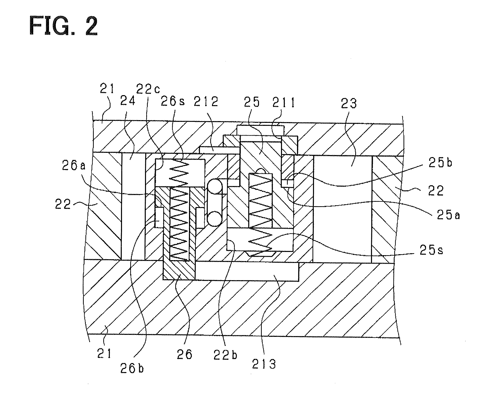
[0039]As shown in the drawings, a variable valve timing device (VVT) 20 is disposed in a drive train for transmitting valve driving force from a crankshaft (output shaft) 10 to a camshaft 14 of an engine. The drive train is provided by a belt drive mechanism including a belt 12 and pulleys. The VVT 20 is provided with a first rotor (housing) 21 which is mechanically connected with the crankshaft 10, and a second rotor (vane rotor) 22 which is mechanically connected with the camshaft 14. The second rotor 22 is provided with a plurality of radially protruded portions (vanes) 22a, and is rotatably housed in an inner chamber defined in the first rotor 21. The VVT 20 includes a plurality of pairs of a retarding chamber 23 and an advancing chamber 24. The retarding chamber 23 retards (−) the relative rotational position when the retarding chamber 23 increases the...

second embodiment

[0112]A VVT in this embodiment does not have the restriction pin 26 and the restriction slot 213 in the above-mentioned first embodiment. Other mechanical configurations are the same as the first embodiment. The COM 41 performs process shown in FIGS. 15 and 16 to determine that whether the lock pin 25 is stuck or not.

[0113]FIG. 15 shows determining process for the LPF of the lock pin 25. The determining process causes the ECU 40 to provide means for determining the LPF. The process is designed to determine the LPF, if the LRC is satisfied and the relative rotation of the rotors 21 and 22 can not be changed from the inside to the outside of the first restricted range W1 defined by the guide slot 212. In other words, the process determines the LPF, if the VVT 20 can not be rotated to an outside region from the first restricted range W1 during the LRC is satisfied.

[0114]In a step S100, it is determined that whether the LRC is satisfied or not. In a step S101, it is determined that whet...

third embodiment

[0118]As shown in FIG. 17, a VVT in a third embodiment does not include the lock slot 211 in the first embodiment. As shown in FIG. 18, the VVT provides a first restricted range W10 provided by the first restriction slot 212 and a second restricted range (additional restricted range) W20 provided by the second restriction slot 213. The ranges W10 and W20 are arranged as shown in FIG. 18. Other configurations are the same as the first embodiment.

[0119]In this embodiment, the VVT includes a first restriction pin 25 and a second restriction pin 26 provided on the second rotor 22. The pins 25 and 26 are projected from the second rotor 22 to the projected position when a restriction-pin-projecting condition provided as the restricting condition is satisfied. The pins 25 and 26 are retracted into the second rotor 22 to the retracted position when a restriction-pin-retracting condition provided as the enabling condition is satisfied. The VVT includes a first restriction slot 212 provided o...


PUM


Abstract

A VVT has a movable restriction member and a restriction slot. When the restriction member is in a projected position, the VVT is variable in a restricted range to which the restriction member can be rotatable within the restriction slot. When the restriction member is in a retracted position, the VVT is variable in a range wider than the restricted range. When a condition where the restriction member shall be projected is satisfied, if the variable range of the VVT reaches beyond the restricted range, the device determines that the restriction member is stuck at the retracted position. When a condition where the restriction member shall be retracted is satisfied, if the variable range of the VVT is restricted in the restricted range, the device determines that the restriction member is stuck at the projected position.

Description

CROSS REFERENCE TO RELATED APPLICATION[0001]This application is based on Japanese Patent Application No. 2009-158754 filed on Jul. 3, 2009, the contents of which are incorporated herein by reference in its entirety.FIELD OF THE INVENTION[0002]The present invention relates to a variable valve timing device which adjusts opening and closing timing of an intake valve or an exhaust valve in an engine.BACKGROUND OF THE INVENTION[0003]A variable valve timing device (VVT) for adjusting opening and closing timing of an intake valve or an exhaust valve in an engine is known. The VVT is applied to the engine which includes a camshaft for operating the intake valve or the exhaust valve, and an engine output shaft, e.g., a crankshaft, which synchronously rotates the camshaft via a drive train such as a belt drive train and a gear train. The VVT may be installed in the drive train for transmitting driving force from the output shaft to the camshaft. The VVT includes a first rotor which rotates w...

Claims


Application Information

Patent Timeline
Patent Type & Authority Applications(United States)
IPC IPC(8): F01L1/34
CPCF01L1/024F01L1/3442F01L2800/01F01L2001/34469F01L2001/34476F01L2001/3443
Inventor URUSHIHATA, HARUYUKIWADA, MINORU
Owner DENSO CORP
Why Eureka
Try Eureka