
Image forming apparatus

a technology of forming apparatus and driving motor, which is applied in the direction of electrographic process apparatus, instruments, optics, etc., can solve the problems of reducing the ease of maintenance and difficulty in placing all of the driving motors behind the developing device, and achieve the effect of reducing the ease of operation

Inactive Publication Date: 2011-01-06
CANON KK
View PDF7 Cites 2 Cited by
  • Summary
  • Abstract
  • Description
  • Claims
  • Application Information

AI Technical Summary

Benefits of technology

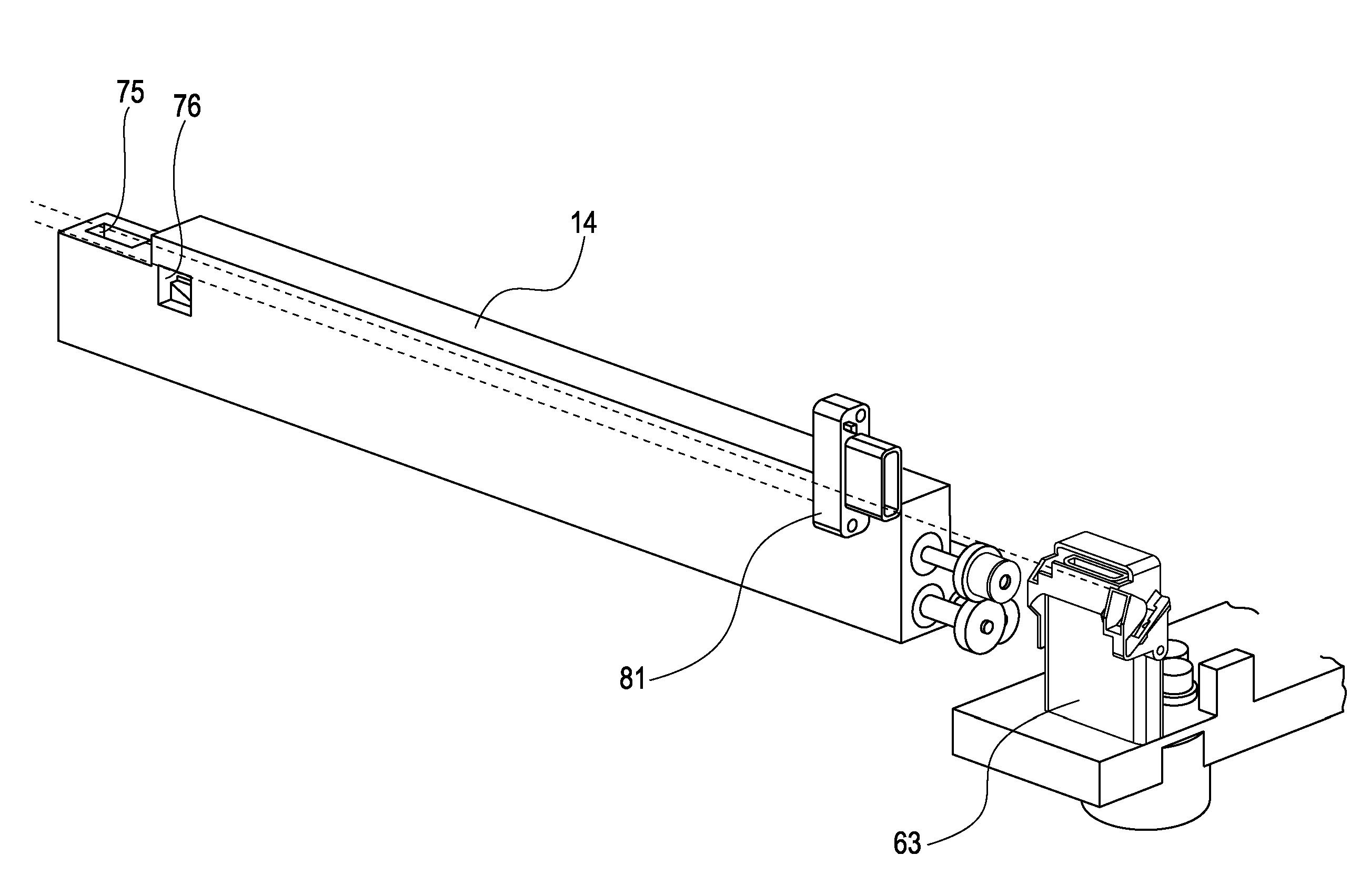
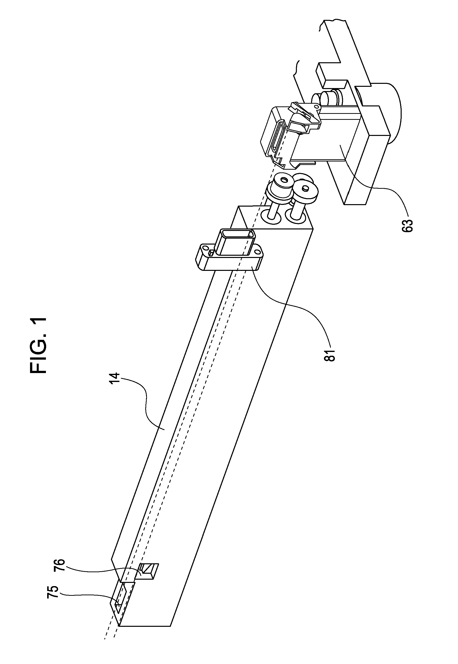
[0009]The present invention provides an image forming apparatus which includes a detachable developing device having an image-developing-agent holding member and a developing-agent conveying member that are driven independently of each other and which allows replacing of the developing device without reducing the ease of operation even when driving motors are disposed in front of and behind the developing device in the direction in which the developing device is detached.

Problems solved by technology

In the case where a plurality of driving motors are provided to drive the developing device, it is difficult to place all of the driving motors behind the developing device because the space is limited.
However, in such a case, the driving motors placed in front of the developing device must be removed to take out the developing device from the main body of the apparatus, and the ease of maintenance is reduced.

Method used


Image

  • Image forming apparatus
  • Image forming apparatus
  • Image forming apparatus

Examples


Embodiment Construction

[0023]An embodiment of the present invention will now be described with reference to the accompanying drawings. The embodiment is described to explain the present invention by way of example, and dimensions, materials, shapes, relative positions, etc., of components described below are not intended to limit the scope of the present invention unless specifically stated otherwise.

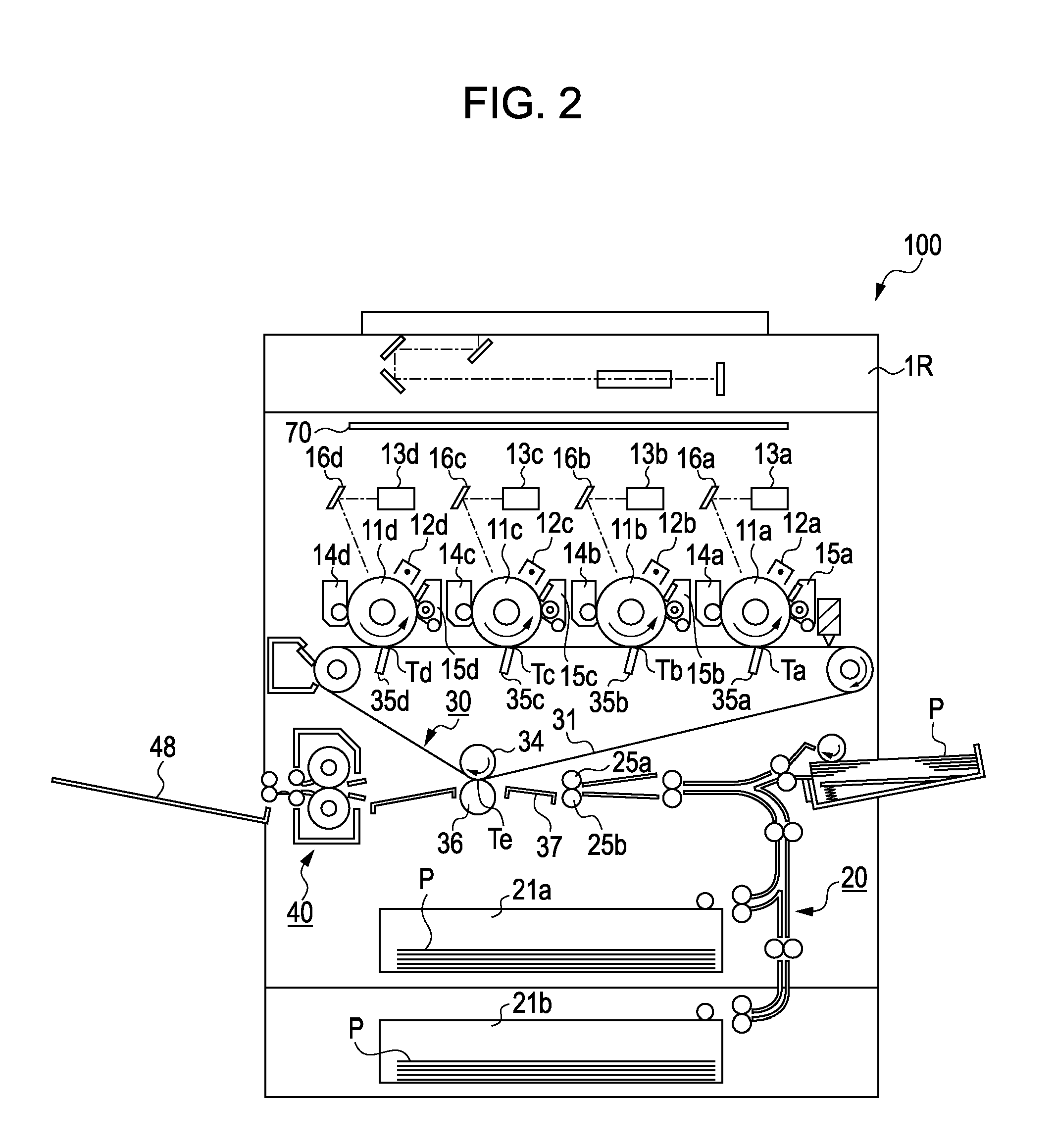
[0024]FIG. 2 shows a schematic sectional view of an image forming apparatus 100 according to the embodiment of the present invention.

[0025]In FIG. 2, photosensitive drums 11a to 11d, which are image bearing members, are supported in a rotatable manner. First charging devices 12a to 12d, laser exposure optical systems 13a to 13d, developing units 14a to 14d, and photosensitive-member cleaners 15a to 15d are disposed around the photosensitive drums 11a to 11d, respectively. An intermediate transfer member 30 is disposed near the photosensitive drums 11a to 11d. The intermediate transfer member 30 includes first...


PUM


Abstract

At least one of driving motors that drive a developing device independently of each other is provided on a door capable of opening and closing to allow the developing device to be attached to or detached from a main body of an apparatus. An electrical contact portion that can be electrically connected to or disconnected from an electrical circuit provided in the main body is provided for the driving motor provided on the door.

Description

BACKGROUND OF THE INVENTION[0001]1. Field of the Invention[0002]The present invention relates to an image forming apparatus including a developing device that is detachably attached to a main body of the image forming apparatus. More particularly, the present invention relates to an image forming apparatus including a plurality of driving units which drive the developing device independently of each other.[0003]2. Description of the Related Art[0004]Recently, there have been increasing demands for color copy machines in offices, and tandem-drum-type copy machines including a plurality of photosensitive drums, which are advantageous in view of printing speed, have become popular. Various types of inner structures are adopted in tandem-drum-type copy machines. For example, a structure in which four photosensitive drums are arranged in a horizontal direction is relatively commonly used.[0005]Japanese Patent Laid-Open No. 2001-222207 discusses an apparatus including an open-close unit t...

Claims


Application Information

Patent Timeline
IPC IPC(8): G03G15/00G03G15/04
CPCG03G2221/163G03G2221/1657G03G2221/166G03G15/0898G03G21/1633G03G21/1652G03G2221/169
Inventor KAKITANI, MASAKI
Owner CANON KK
Learn More