Reference frame fixator

a reference frame and fixator technology, applied in the field of computer assisted surgery, can solve the problems of stress risers in the bone, additional openings, and reference frames superior or inferior to the joint, and achieve the effect of reducing the risk of fracture, and reducing the accuracy of the procedur

Inactive Publication Date: 2011-01-06
SMITH & NEPHEW INC
View PDF0 Cites 28 Cited by
  • Summary
  • Abstract
  • Description
  • Claims
  • Application Information

AI Technical Summary

Problems solved by technology

Because the reference frames are directly fixed to the bone through the percutaneous pins, the size and depth of the pins may cause stress risers in the bone.
In addition, when using percutaneous pins, there is a potential to hit nerves, arteries and other structures resulting in injury, as well as introduce additional openings for infection.
Moreover, the use of percutaneous pins may also block the intramedullary (IM) canal, which may cause problems in fixation if a prosthesis uses an IM fixator, or may cause problems if additional alignment through the IM canal is used for component placement and bone resection guidance.
However, as previously noted, the placement of the reference frame superior or inferior to the joint creates additional problems through stress risers, soft tissue injuries, additional sites of possible infection, and IM canal blockage.

Method used


Image

  • Reference frame fixator
  • Reference frame fixator
  • Reference frame fixator

Examples


Embodiment Construction

[0020]The following description of the preferred embodiment(s) is merely exemplary in nature and is in no way intended to limit the invention, its application, or uses.

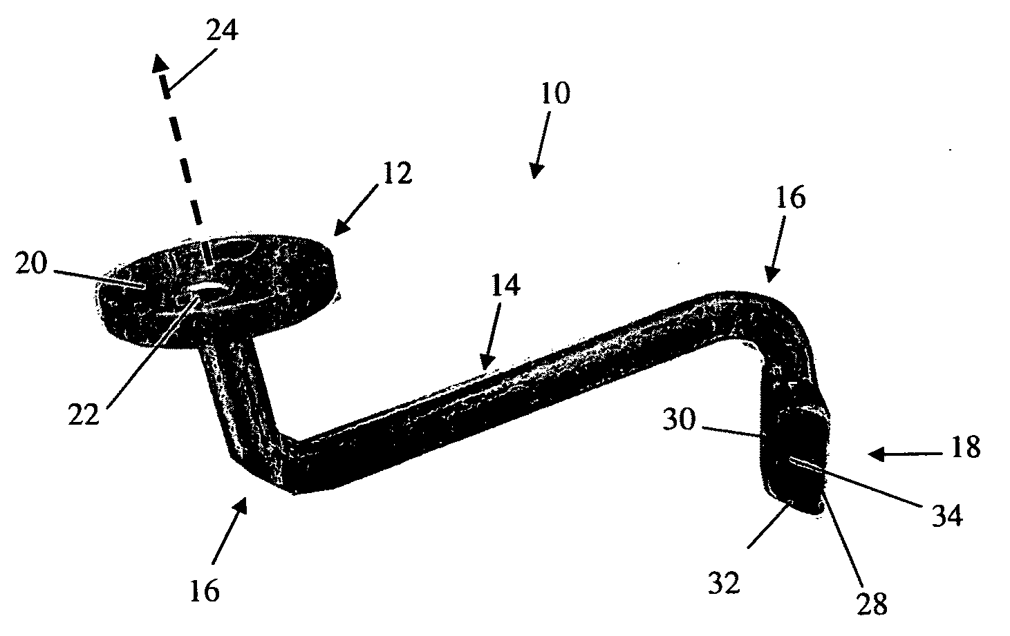
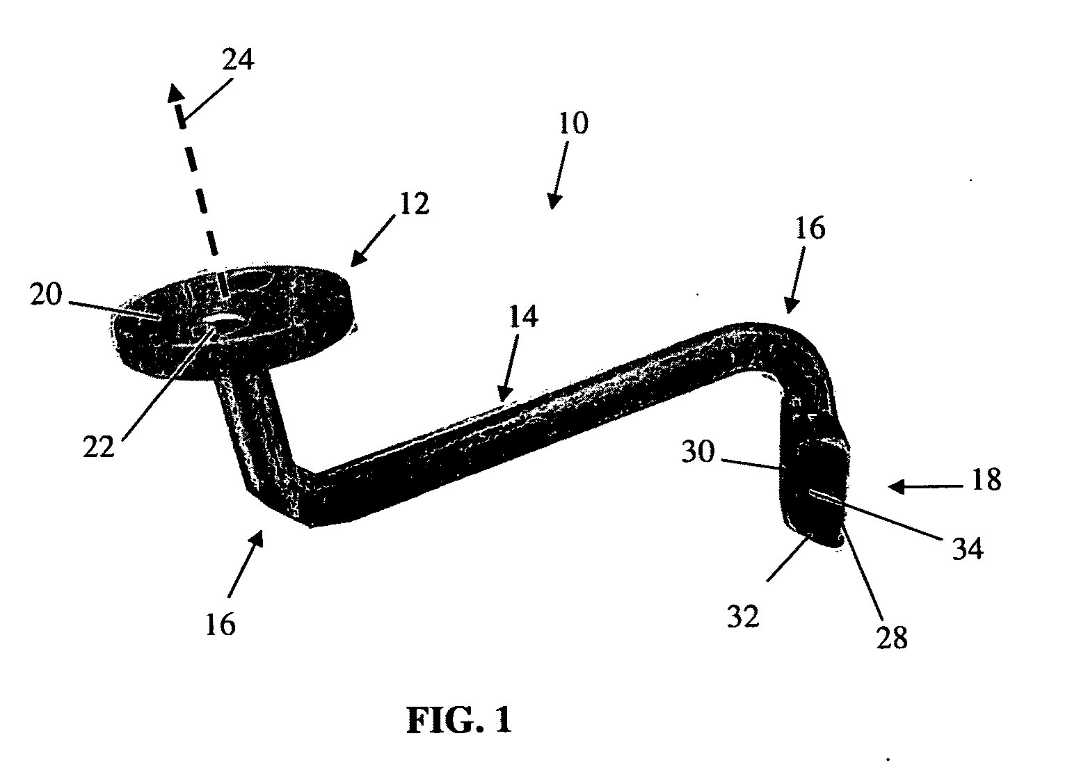
[0021]Turning now to FIG. 1, FIG. 1 is a view of an embodiment of a fiducial base 10 according to an aspect of the invention. The fiducial base 10 includes a marker platform 12, an extending arm 14, turns 16, and a male base fixation member 18. The marker platform 12 is configured to couple a fiducial marker to the fiducial base 10. The extending arm 14 spaces the fiducial marker attached to the marker platform 12 away from the male base fixation member 18 according to the number, direction, and degrees of the turns 16. The male base fixation member 18 couples the fiducial base 10 to a bone fixation member, which then couples the fiducial base 10 to a bone.

[0022]The extending arm 14 and the turns 16 may be sized according to a desired end position of the fiducial marker. By specifying the length of the extending arm 1...


PUM


Abstract

A device for positioning a fiducial marker (160) on an anatomical structure includes a fiducial base (40) and a fixation member (60). The fiducial base (40) comprises a turn (44) and an extension (42) configured to position the fiducial marker (160) within the field of view of a tracking sensor (210). The fiducial marker (160) is positioned away from the anatomical structure. The fixation member (60) is configured to have a low profile and further configured to fix the fiducial base (40) to the anatomical structure. The fixation member (60) is fixed to the anatomical structure through a primary surgical incision and positioned on the anatomical structure such that the fixation member (60) is isolated from the surgical approach. The fiducial base (40) extends from the fixation member through the primary surgical incision.

Description

CROSS-REFERENCE TO RELATED APPLICATIONS[0001]This application claims priority to U.S. Provisional Patent Application No. 60 / 866,316 filed on Nov. 17, 2006. The disclosure of this prior application is incorporated by reference in its entirety.BACKGROUND[0002]1. Field[0003]The present invention relates generally to computer assisted surgery and more particularly to reference frames for capturing positions in computer assisted surgery.[0004]2. Related Art[0005]Many reference frames are fixed to a patient through percutaneous pins placed through the quad muscles into the tibia. The reference frames are attached to tracking devices for surgical navigation. Because the reference frames are directly fixed to the bone through the percutaneous pins, the size and depth of the pins may cause stress risers in the bone. In addition, when using percutaneous pins, there is a potential to hit nerves, arteries and other structures resulting in injury, as well as introduce additional openings for inf...

Claims


Application Information

Patent Timeline
Patent Type & Authority Applications(United States)
IPC IPC(8): A61B17/56
CPCA61B17/809A61B19/54A61B2019/5483A61B2019/5416A61B2019/5287A61B2090/3983A61B2090/363A61B2090/3916A61B90/39
Inventor STALLINGS, JODYTRIA, ALFRED
Owner SMITH & NEPHEW INC
Why Eureka
Try Eureka