
Zoom optical system, optical apparatus equipped therewith and method for manufacturing the zoom optical system

Active Publication Date: 2011-01-13
NIKON CORP
View PDF1 Cites 31 Cited by
  • Summary
  • Abstract
  • Description
  • Claims
  • Application Information

AI Technical Summary

Benefits of technology

[0007]The present invention is made in view of the above described problem, and has an object to provide a zoom optical system capable of coping with the problem of variation in aberrations upon zooming and obtaining excellent optical performance, an optical apparatus equipped with the zoom optical system, and a method for manufacturing the zoom optical system.
[0026]With constructing the zoom optical system, an optical apparatus equipped with the zoom optical system, and a method for manufacturing the zoom optical system as described above, it becomes possible to obtain excellent optical performance capable of coping with variation in aberrations upon zooming.

Problems solved by technology

However, the conventional zoom optical system has had a problem that variation in aberrations upon zooming is large.

Method used


Image

  • Zoom optical system, optical apparatus equipped therewith and method for manufacturing the zoom optical system
  • Zoom optical system, optical apparatus equipped therewith and method for manufacturing the zoom optical system
  • Zoom optical system, optical apparatus equipped therewith and method for manufacturing the zoom optical system

Examples


example 1

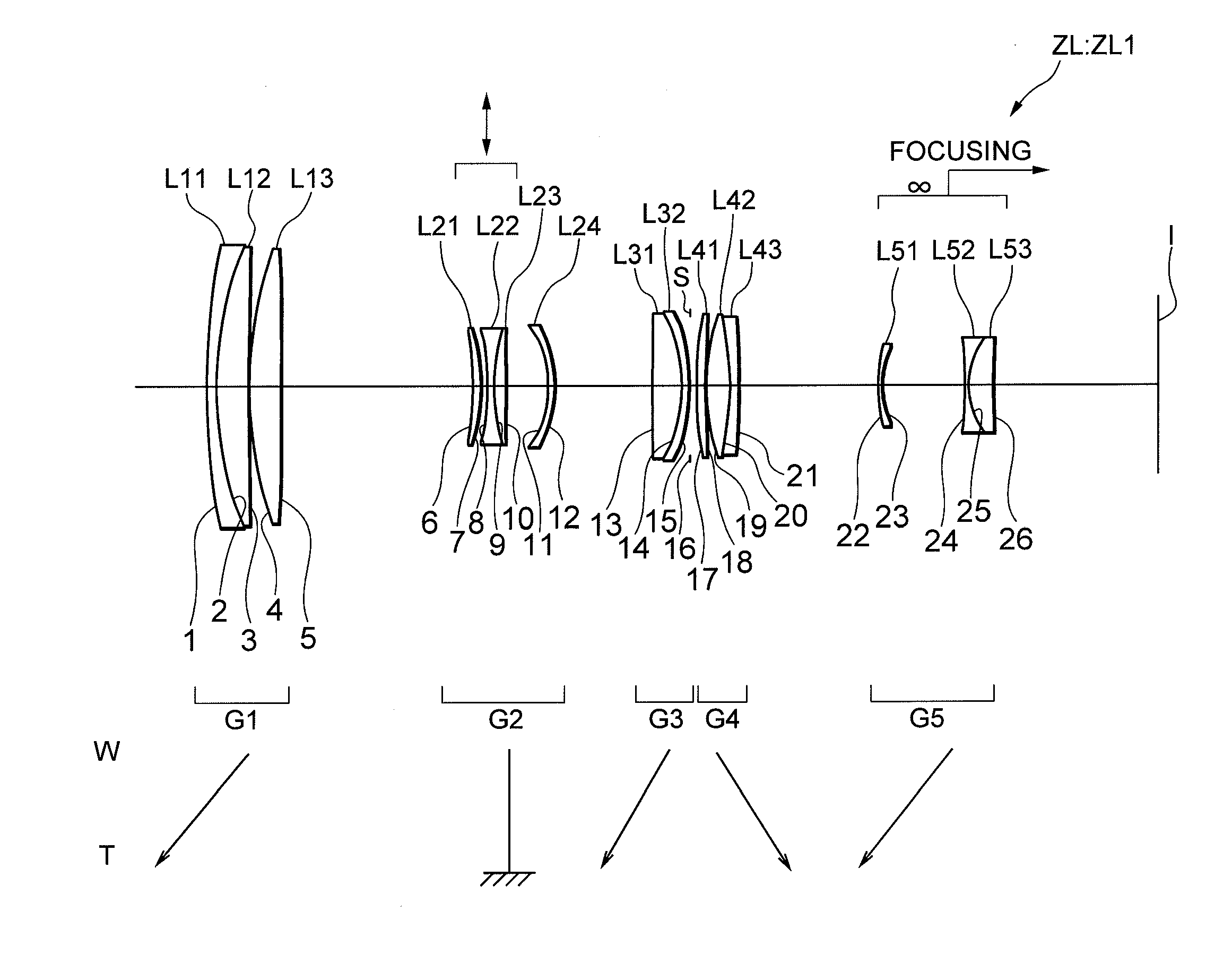
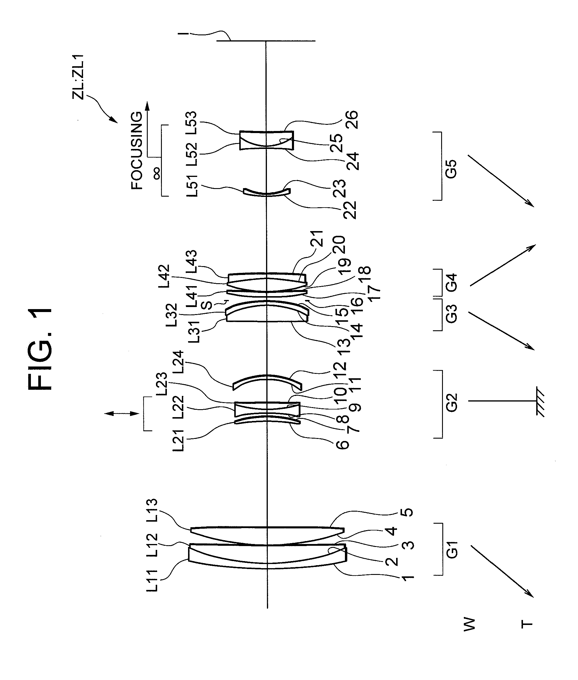
[0057]FIG. 1 is a sectional view showing a lens configuration of a zoom optical system ZL1 according to Example 1. In the zoom optical system ZL1 shown in FIG. 1, the first lens group G1 is composed of, in order from an object side, a cemented lens constructed by a negative meniscus lens L11 having a concave surface facing an image side cemented with a positive meniscus lens L12 having a convex surface facing the object side, and a double convex positive lens L13. The second lens group G2 is composed of, in order from the object side, a positive meniscus lens L21 having a convex surface facing the image side, a cemented lens constructed by a double concave negative lens L22 cemented with a positive meniscus lens L23 having a convex surface facing the object side, and a negative meniscus lens L24 having a concave surface facing the object side. The third lens group G3 is composed of a cemented lens constructed by, in order from the object side, a double convex positive lens L31 cemen...

example 2

[0060]FIG. 4 is a sectional view showing a lens configuration of a zoom optical system ZL2 according to Example 2. In the zoom optical system ZL2 shown in FIG. 4, a first lens group G1 is composed of, in order from an object side, a cemented lens constructed by a negative meniscus lens L11 having a concave surface facing an image side cemented with a double convex positive lens L12, and a double convex positive lens L13. A second lens group G2 is composed of, in order from the object side, a positive meniscus lens L21 having a convex surface facing the image side, a cemented lens constructed by a double concave negative lens L22 cemented with a positive meniscus lens L23 having a convex surface facing the object side, and a negative meniscus lens L24 having a concave surface facing the object side. A third lens group G3 is composed of a cemented lens constructed by, in order from the object side, a double convex positive lens L31 cemented with a negative meniscus lens L32 having a c...

example 3

[0063]FIG. 7 is a sectional view showing a lens configuration of a zoom optical system ZL3 according to Example 3. In the zoom optical system ZL3 shown in FIG. 7, a first lens group G1 is composed of, in order from an object side, a cemented lens constructed by a negative meniscus lens L11 having a concave surface facing an image side cemented with a positive meniscus lens L12 having a convex surface facing the object side, and a double convex positive lens L13. A second lens group G2 is composed of, in order from the object side, a positive meniscus lens L21 having a convex surface facing the image side, a cemented lens constructed by a positive meniscus lens L22 having a convex surface facing the image side cemented with a double concave negative lens L23, and a cemented lens constructed by a double concave negative lens L24 cemented with a double convex positive lens L25. A third lens group G3 is composed of, in order from the object side, a double convex positive lens L31, and a...


PUM


Abstract

Composing a zoom optical system ZL, in order from an object side, a first lens group G1 having positive refractive power, a second lens group G2 having negative refractive power, a third lens group G3 having positive refractive power, a fourth lens group G4 having positive refractive power, and a fifth lens group G5 having negative refractive power; and disposing each lens group with satisfying a given conditional expression (1); thereby providing a zoom optical system ZL capable of suppressing variation in aberrations upon zooming and carrying out excellent vibration reduction, an optical apparatus equipped therewith, and a method for manufacturing the zoom optical system.

Description

[0001]The disclosure of the following priority application is herein incorporated by reference:[0002]Japanese Patent Application No. 2009-162681 filed on Jul. 9, 2009.BACKGROUND OF THE INVENTION[0003]1. Field of the Invention[0004]The present invention relates to a zoom optical system, an optical apparatus equipped with the zoom optical system, and a method for manufacturing the zoom optical system.[0005]2. Related Background Art[0006]There have been proposed zoom optical systems suitable for a film camera, an electronic still camera, a video camera, and the like disclosed in such as a Japanese Patent Application Laid-Open No. 2003-344768. However, the conventional zoom optical system has had a problem that variation in aberrations upon zooming is large.SUMMARY OF THE INVENTION[0007]The present invention is made in view of the above described problem, and has an object to provide a zoom optical system capable of coping with the problem of variation in aberrations upon zooming and ob...

Claims


Application Information

Patent Timeline
IPC IPC(8): G02B15/14
CPCG02B15/173G02B15/145113
Inventor MATSUO, TAKU
Owner NIKON CORP
Features
  • Generate Ideas
  • Intellectual Property
  • Life Sciences
  • Materials
  • Tech Scout
  • Unparalleled Data Quality
  • Higher Quality Content
  • 60% Fewer Hallucinations
Learn More