
System, method and apparatus for illuminating a bezel

a technology of illuminating bezels and systems, applied in television systems, instruments, color signal processing circuits, etc., can solve problems such as eye strain, difficult to address, and difficult to predi

Active Publication Date: 2011-01-27
VIZIO INC
View PDF6 Cites 33 Cited by
  • Summary
  • Abstract
  • Description
  • Claims
  • Application Information

AI Technical Summary

Benefits of technology

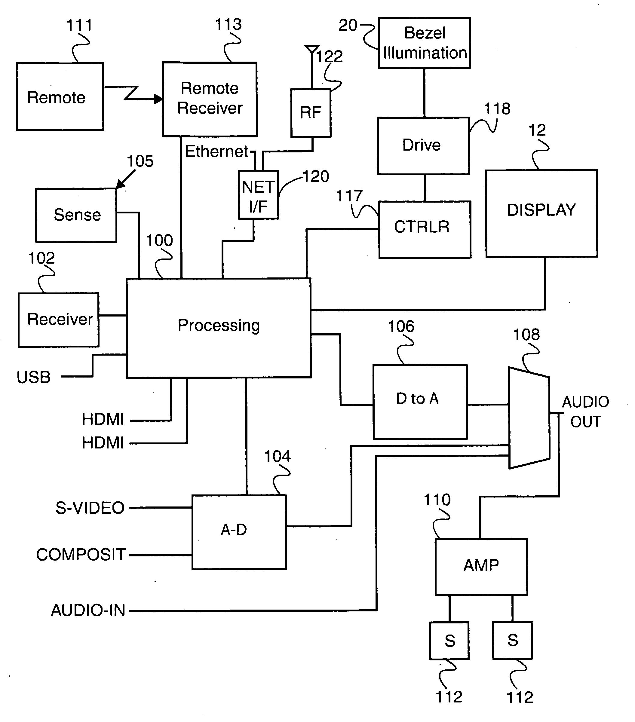
The present invention is about a bezel with internal lighting that can be adjusted based on user preferences, external parameters, or internal parameters like time and content being viewed. The bezel is made of a material that can transmit light from within to outside. There are also at least one illuminating element behind the bezel that can be controlled to emit light. The processing element displays an on-screen display responsive to an input device, and the user can select the brightness of each illuminating element. The illuminated bezel is mounted on the monitor / television and made of a material that can transmit light. The illuminating elements are positioned so that when they are energized, some of the light passes through the bezel. This invention provides a unique way to enhance the display of the monitor / television with an illuminated bezel.

Problems solved by technology

In some cases, a strongly contrasting bezel may lead to eye strain.
This contrast issue is difficult to address with a fixed-color bezel, since it is difficult to predict what will be displayed in the display area of the monitor / television.
For example, a light-colored bezel would blend well with text displayed on a white page but would not blend well with a movie, especially during scenes that are dark.
Likewise, a dark or black colored bezel would blend well with the movie but would be distracting when viewing, for example, text on a white page.
This solution does not provide for varying the bezel color / appearance with respect to variations of the displayed subject matter, does not provide indications of internal metadata or status and does not solve the problem of a varying environment such as daytime vs. nighttime viewing.
Furthermore, this solution is limited to a small set of bezel colors.

Method used


Image

  • System, method and apparatus for illuminating a bezel
  • System, method and apparatus for illuminating a bezel
  • System, method and apparatus for illuminating a bezel

Examples


Embodiment Construction

[0023]Reference will now be made in detail to the presently preferred embodiments of the invention, examples of which are illustrated in the accompanying drawings. Throughout the following detailed description, the same reference numerals refer to the same elements in all figures. The bezel of the present invention is the facing surface surrounding an image producing surface such as an LCD panel, CRT, Plasma panel, OLED panel and the like.

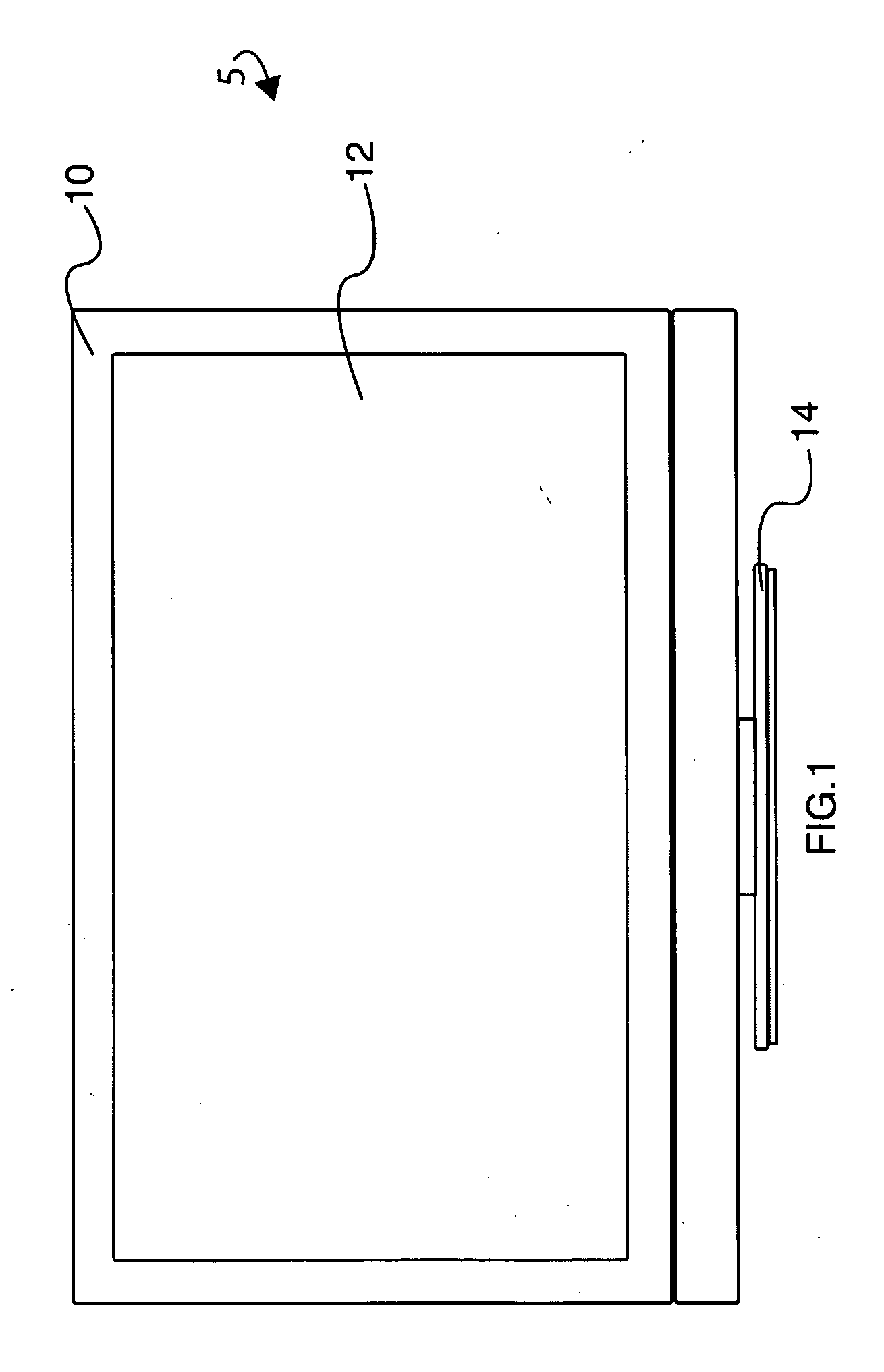
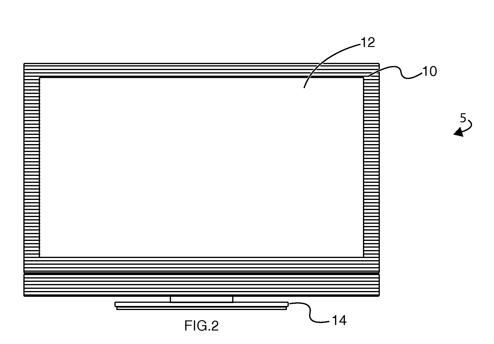
[0024]Referring to FIG. 1, a plan view of a monitor / television 5 with bezel 10 of the present invention will be described. The present invention is applicable to any display device that has a bezel such as a monitor / television 5. Typically, the bezel 10 is situated around the peripheral edge of the display panel 12, covering the frame and electronics 13 (see FIG. 4) of the display panel 12. For completeness, though not required in the present invention, the monitor / television is shown on a stand 14. In this view, the bezel 10 is of a first color.

[0...


PUM


Abstract

An application for a bezel with internal lighting includes at least one illuminated element situated behind a monitor / television bezel. The brightness and color of the illuminating elements and hence the bezel appearance are modified based upon either user preference or an internal or external parameters such as time, content being viewed, recording status, etc.

Description

CROSS-REFERENCE TO RELATED APPLICATION[0001]This application is related to U.S. application titled, “SYSTEM, METHOD AND APPARATUS FOR IMBEDDING A DISPLAY IN A BEZEL,” which was filed on even date herewith; attorney docket number 90104 and inventors Kenneth Lowe, Matthew Blake McRae and John Schindler.FIELD OF THE INVENTION[0002]This invention relates to the field of display devices and more particularly to a system for illuminating the bezel of a display device.BACKGROUND OF THE INVENTION[0003]Monitor / television devices such as LCD or Plasma televisions have a bezel surrounding the actual display device (LCD panel, Plasma panel, CRT, etc). There have been many colors and varieties of bezels. Most bezels on current monitor / television products are black, while bezels on notebook computers and monitors are often colored to match the color of the shell of the notebook computer or monitor, sometimes white, black, dark blue, etc.[0004]There are many reasons for different bezel appearances...

Claims


Application Information

Patent Timeline
Patent Type & Authority Applications(United States)
IPC IPC(8): H05B37/02F21S4/00F21V9/00F21V11/00
CPCF21V23/04H04N21/84G02F1/133308G02F2001/13332H04N5/58H04N5/64H04N9/67H04N9/30H04N21/4131H04N21/42202H04N21/42221H04N21/4532H04N21/478H04N21/4786H04N21/485F21Y2101/02F21Y2101/00F21Y2115/10F21Y2115/15G02F1/13332
Inventor LOWE, KENNETHMCRAE, MATTHEW BLAKESCHINDLER, JOHN
Owner VIZIO INC
Learn More