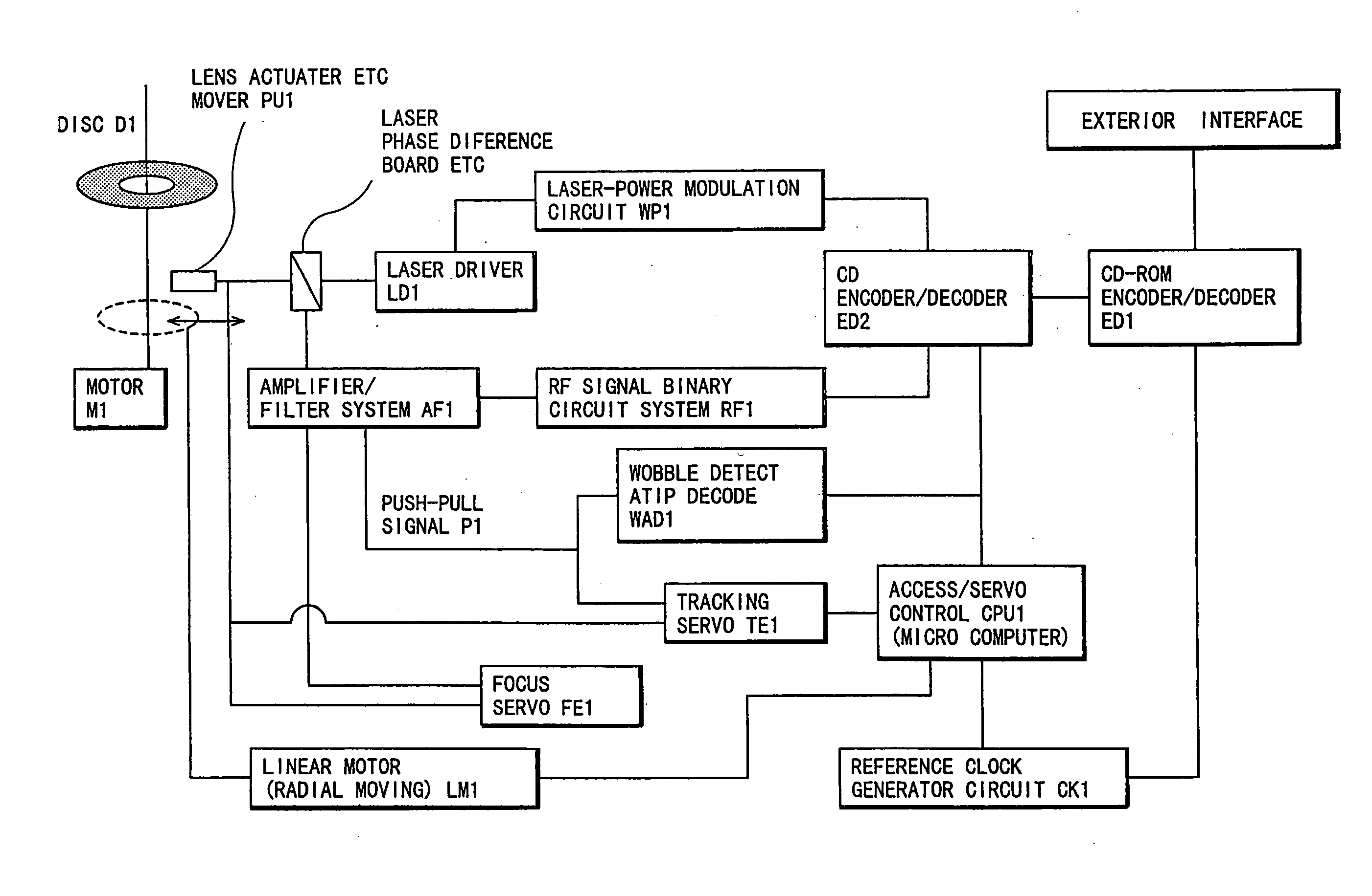
One of the common problems with CD-RW is slowness of the recording speed and data transfer rate.
However, such CD-RW enabling recording at higher linear velocities has not yet been realized.
It has been technically difficult to realize a medium that enables overwriting through a wide linear velocity range, whose
low speed end is 1- and 2-times velocities and high speed end is 8-to 10-times velocities, without any risk of impairing the read-compatibility with existing CD-RW
recording system overwritable at between 1- and 4-times velocity.
The first problem is that it is difficult to resolve a trade-off in short-time erasure requirement by high-speed
crystallization of amorphous marks and archival stability requirement of amorphous marks.
But according to studies of the present inventors, simply increasing the content of Sb would seriously impair the archival stability of amorphous marks so that the amorphous marks would disappear so as to be no longer retrievable within 1 or 2 years in
room temperature and otherwise within several days in a high-temperature environment of 50-80.degree. C. inside the recording apparatus.
More serious, it turned out that amorphous marks would begin to disappear when retrieving has been repeated hundreds to thousands times by
irradiation with
laser beam with the power below 1 mW so that reliability for a recording medium could not be guaranteed.
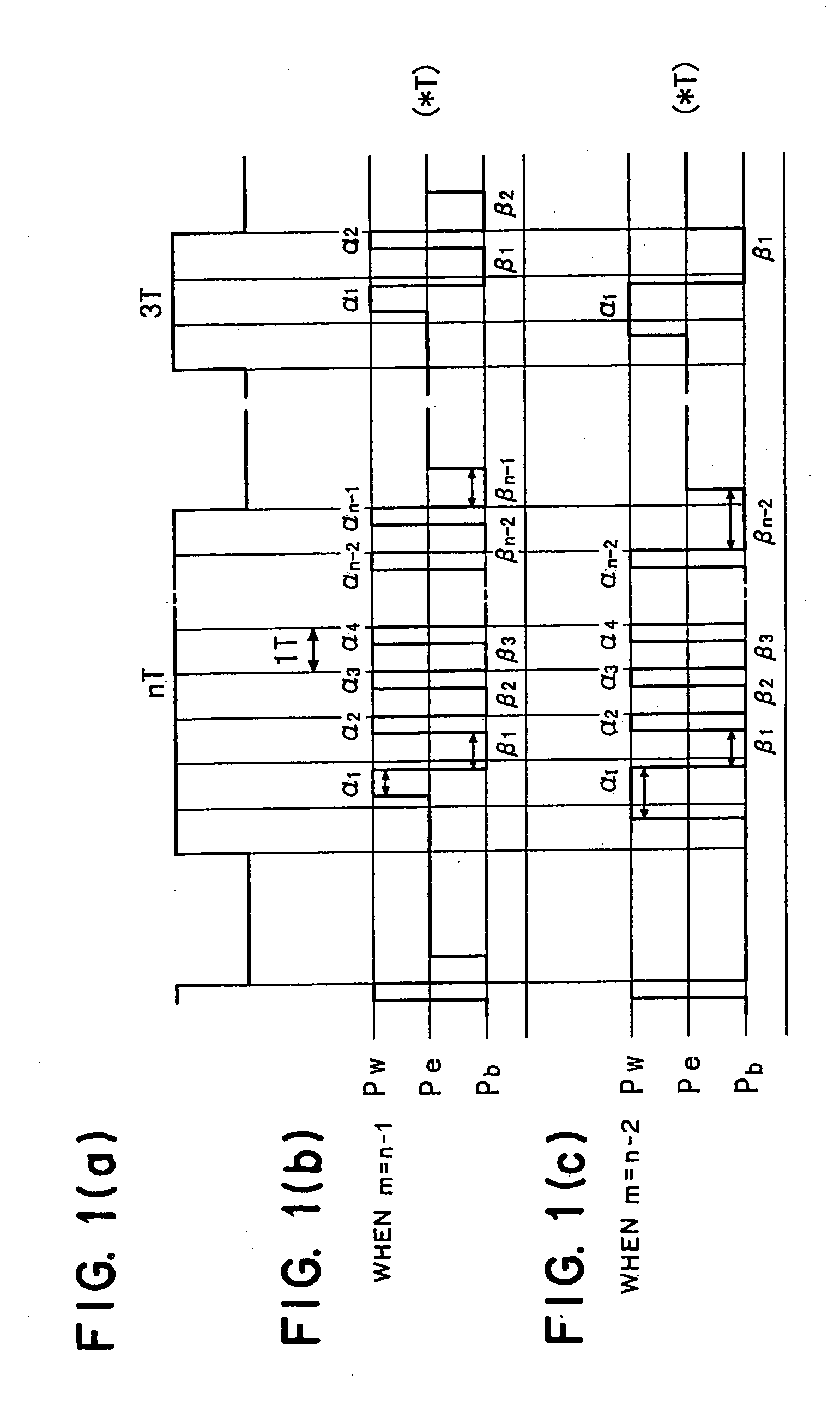
The second problem is that according to CD-RW specifications, fairly strict recording pulse strategies (divided pulse method) are standardized.
Since many of the current CD-RW writers recordable at 4-times velocity can generate only a fixed waveform in accordance with the recording pulse strategy defined in the above-mentioned specifications, it was very difficult to realize high-speed recording at least at 8-through 10-times velocities without any risk of impairing the read-compatibility with these existing writers.
Further, regarding the definition of ".alpha..sub.i+.beta..sub.i-1=-1.0" in each of recording methods 1 through 3, (.alpha..sub.i+.beta..sub.i--1) means a time length equivalent to a reference
clock period T and may include an inevitable error that unavoidably results from the
circuit design.
On the other hand, if the amount of Ge is excessive, since supposedly an inter-metallic compound, such as GeTe or
GeSbTe, is precipitated,
crystal grains having different optical constants are intermingled in the recording layer to increase
noise of the recording layer, which would occasionally be a cause for an increased
jitter.
If excess Sb is too less in amount, the recrystallization speed would be too slow so that comfortable overwriting cannot be achieved a high linear velocity such as 8-times or higher velocity.
On the other hand, if the amount of excess Sb is too large, the recrystallization speed would be too fast so that a qualified amorphous mark can hardly be formed at the 4-times velocity in the divided pulse method according to CD-RW specifications, thus resulting in an remarkably increased
jitter.
However, if the amount of element M is too large, segregation of a particular substance would tend to occur with time and due to repeated overwriting.
If segregation has once occurred, the stability of amorphous structure and the recrystallization speed which the recording layer initially has would change so that the required overwriting characteristic cannot be secured.
But, since excess Sb is added, the
crystallization speed would be too slow to make high-speed recording at 4-times or higher velocity and hence the erasure ratio would be too low to make overwriting.
Namely, even if only the amount of Sb is adjusted, it would be difficult to realize overwriting at 2- through 4-times velocities without risk of impairing the read-compatibility with CD-RW specifications.
Yet, if a recording medium is designed to meet the 4-times velocity, it would be difficult to achieve good recording characteristics by the same strategy at the 8-times velocity.
This is true because it is difficult to make two demands, the high-speed crystallization velocity during high-linear-velocity overwriting and the stability of an amorphous mark, read-compatible with each other.
On the other hand, phase separation of different phase of crystalline is obtained so that it is difficult to obtain such preferred signal phase crystalline structure, when the scanning speed is approximately 30% or more below the maximum overwritable speed of the phase-change media.
If the thickness of the lower protective layer of the recording layer is too thin, sufficient contrast between the
crystal state and the amorphous state can hardly achieved is too small, repeated-overwrite durability tends to suddenly become worse.
Therefore it is optically meaningless to increase the film thickness of the lower protective layer recklessly, which would cause an increase in cost of material and a groove coverage due to the deposition of a thick film.
If the upper protective layer is too thin, the recording layer tends to be damaged due to the deformation of itself when melted, and the power needed for recording tends to become unnecessarily large because the heat
radiation effect is too large.
On the contrary, if the upper protective layer is too thick, temperature distribution inside it would become steep so that the extent of deformation of the protective layer per se can be large, which deformation tends to be accumulated by overwriting.
If the recording layer is too thin, sufficient contrast between recorded and unrecorded states can hardly be achieved, and the crystallization speed tends to become slow.
And erasur of recording in short time tends to become difficult.
Yet if the recording layer is too thick, sufficient
reflectivity contrast between recorded and unrecorded states can hardly be achieved, and the recording sensitivity can be impaired since
heat capacity becomes increased.
Further, the thicker the recording layer, change in volume of the recording layer with crystalline-
amorphous phase change becomes larger; if the recording layer is too thick, microscopic deformation would be accumulated in the protective layer and the
substrate surface during repeated overwriting, which can be a cause for
noise increase.
On the other hand, a material whose volume resistivity is small to a minimum is substantially difficult to obtain; consequently the volume resistivity is usually 20 n.
OMEGA..multidot.m or more.
If it is too thick, even though the sheet resistivity can be reduced, not only adequate heat
radiation effect cannot be achieved, but also the recording sensitivity tends to become worse.
In such thick film, it takes time to deposit the film, so the material cost tends to rise.
Yet if the film thickness is too small, the reflectivity and heat
conductivity will become smaller due to the island-shaped structure at the beginning of
crystal growth.
Regarding the Al
alloy, if an amount of added impurities is too small,
hillock resistance is often inadequate, depending on the deposition condition.
Otherwise if it is too large, the above-mentioned low resistivity is difficult to obtained.
However, if the content of Mn per se is large, Al.sub.6Mn is deposited in the
reflective layer with time to cause the heat
conductivity to vary with time.
Ti is effective to prevent fluctuation of the
sputtering rate, but if its content is too much, Ti causes the heat
conductivity to decrease, and a bulk containing Ti microscopically uniformly distributed is difficult to cast, increasing the target cost; therefore the content is usually 0.2% by weight or less.
On the other hand, pure
metal of Al or Ag tends to be deteriorated in
corrosion resistance and
hillock resistance.
If it is too small in thickness, the interfacial layer is inadequate in protection effect.
Otherwise if it is too large in thickness, the interfacial layer tends to be inadequate in heat
radiation effect.
If it is too thin, the Ag-containing layer is inadequate in heat
radiation effect, and if it is too thick, the Ag-containing layer tends to be inadequate in erasure.
If it is too thick, the interfacial oxidation layer serves as a
heat resistance so that the originally intended function of the reflectively layer, which is high in heat radiation, can be impaired.
Namely, adjustment in volume resistivity by combining different metals together can simplify the
sputtering process with use of an
alloy target and, at the same time, would rather cause a rise of the target manufacturing cost and an increase of
raw material ratio of the medium.
If the groove depth is too large, the push-pull signal value after recording tends to become too large, and the radial contrast value after recording tends to become too large as compared that value before recording so that the
servo stability can be encountered with a problem.
Otherwise if the groove depth is too small, the radial contrast value and the push-pull value can become smaller than a minimum value requested in CD-RW specification such as Orange Book, Part 3, and the constraint effect of the recording layer by the groove wall becomes worse so that deterioration of the constraint effect due to repeated overwriting would tend to be promoted.
Otherwise if the groove depth is too small, it would be difficult to manufacture the stamper and to mold the substrate.
If the
groove width is too small, the absolute value of radial contrast after recording becomes difficult to satisfy a value of less than 0.6 in CDS-RW specifications.
Otherwise if the
groove width is too large, deterioration of overwriting durability due to the wobble tends to become remarkable.
In general, it is presumed that deterioration due to heat damage during repeated overwriting tends to occur as
stress concentration tends to occur at the groove walls and groove corners where the tightness of contact with the confronting thin film is inadequate.
And when even part of
light beam irradiates such portions, deterioration tends to be rather promoted.
Nonetheless, when recording mark-length-modulated data on a phase-change medium in terms of mark and inter-mark lengths, the ratio of the maximum effective linear velocity to the minimum effective linear velocity is practically limited to roughly 2 for the fixed recording pulse strategy.
If .alpha..sub.iT or .beta..sub.iT is too small, the rising time and falling time of recording
laser in the current ordinary recording apparatus are preferably at least 2, 3 ns; therefore, accurate adjustment of the pulse is difficult to achieve.
If the off-pulse section .beta..sub.iT (i=from 1 to m-1) is too small, the
cooling rate of the recording layer can be inadequate.
Here the method of (3) above can be applied also for 10-times or higher linear velocity, but it can be difficult to control
laser pulses accurately as the data reference lock period becomes shorter with respect to the high linear velocity.
The recording laser
pulse generator circuit would be difficult to follow unless the velocity is extremely high.
This recording method enables recording with CD-RW not only in CLV mode but in CAV mode; hitherto it was possible only in CLV mode, requiring synchronization in rotation all the time during recording, which would be poor in user data area and seek performance as the week point of CD-RW media.
Further, hitherto in CLV recording, a large power would be consumed as the motor is speeded up and slowed down due to the variation of angular speed.
In general, multiplying a frequency by 100 or more encounters with error.
Therefore, it is difficult to sort out the
clock mark frequency throughout the entire recording area by a
single band-pass filter.


