Charge pump circuit
a pump circuit and discharge pump technology, applied in the direction of power conversion systems, instruments, dc-dc conversion, etc., can solve the problems of difficult to accurately predict the exact leakage current and limited bias voltag
- Summary
- Abstract
- Description
- Claims
- Application Information
AI Technical Summary
Problems solved by technology
Method used
Image

Examples
Embodiment Construction
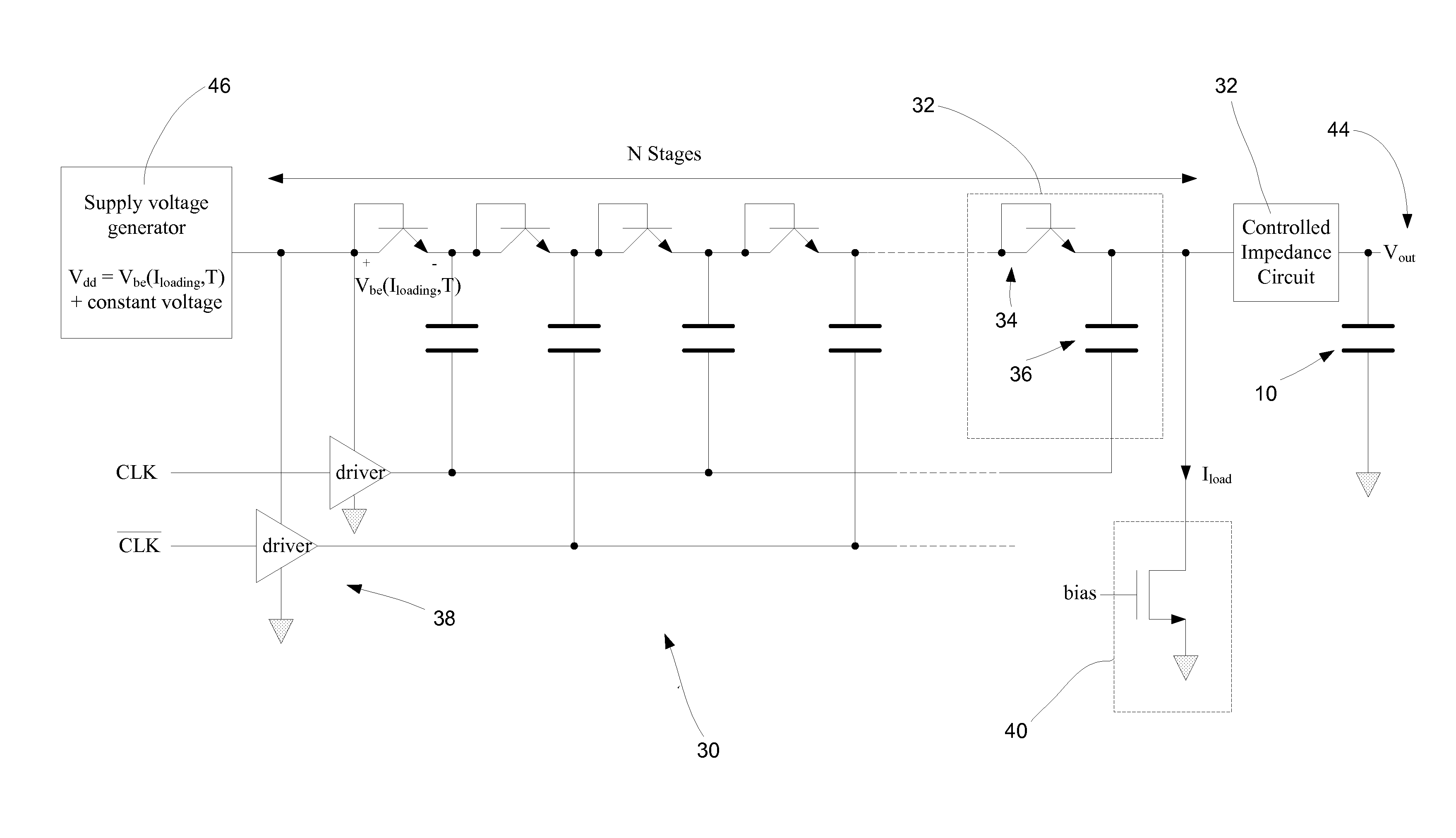
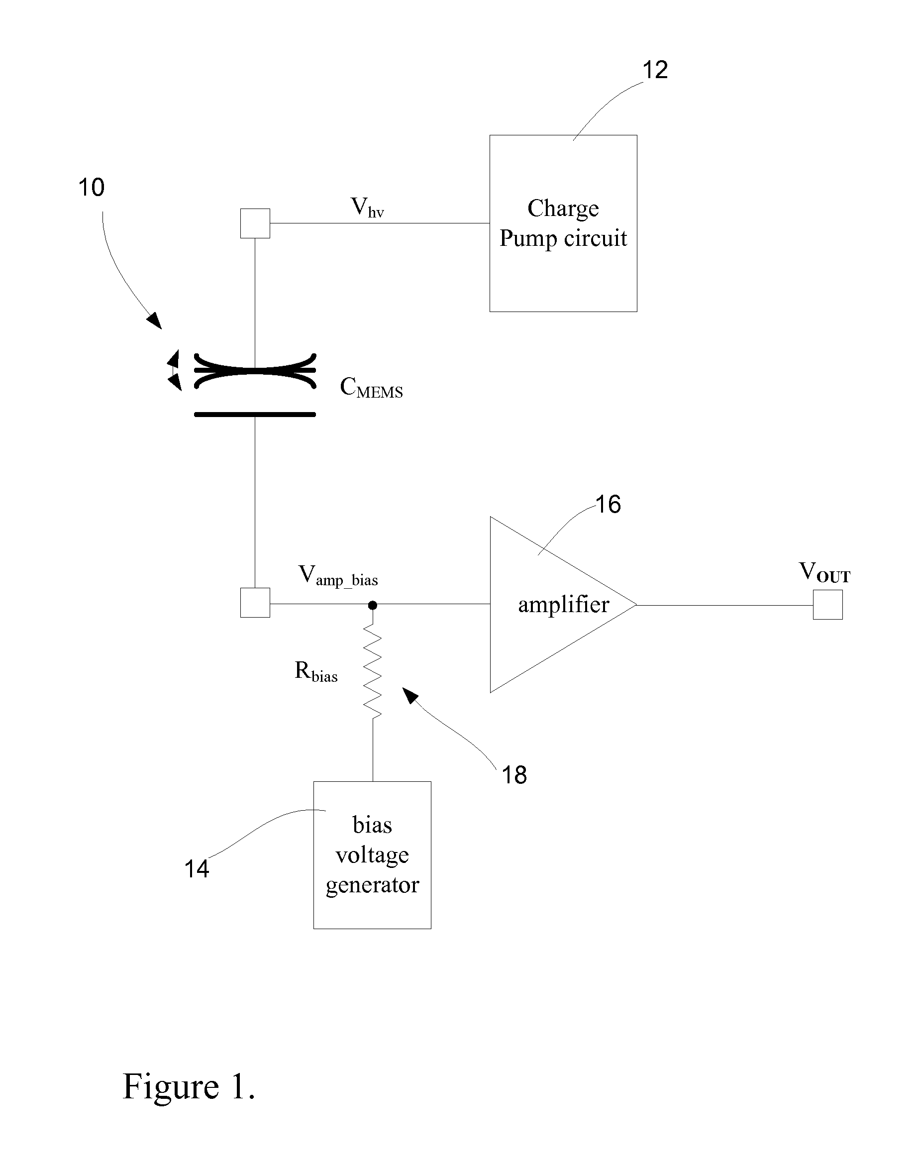
[0045]With reference now to FIG. 6 of the drawings, there is shown an example of a charge pump circuit 30. The charge pump circuit 30 is typically used for biasing a capacitive transducer, such as a MEMS microphone. FIG. 1, as described above, shown one example of the application of the charge pump circuit 30.
[0046]The charge pump circuit 30 typically includes a plurality of parallel arranged transistor-capacitor units generally shown at 32. Each unit 32 has a bipolar junction transistor 34 with a collector terminal connected to a base terminal and an emitter terminal connected to a capacitor 36.
[0047]The charge pump circuit 30 also includes drive circuitry 38 for driving the transistor-capacitor units 32 at a predetermined rate. Also included is load current circuitry 40 connected to a last transistor-capacitor unit, as shown. The load current circuitry 40 is configured to determine a load current through the transistor-capacitor units 32 in order to establish a controllable voltag...
PUM
 Abstract
Description
Claims
Application Information
 - R&D Engineer
- R&D Manager
- IP Professional
- Industry Leading Data Capabilities
- Powerful AI technology
- Patent DNA Extraction
Browse by: Latest US Patents, China's latest patents, Technical Efficacy Thesaurus, Application Domain, Technology Topic.
© 2024 PatSnap. All rights reserved.Legal|Privacy policy|Modern Slavery Act Transparency Statement|Sitemap