
Air pump for inflatable article

Active Publication Date: 2011-01-27
DONGGUAN TIGER POINT METAL & PLASTIC PRODS
View PDF3 Cites 29 Cited by
  • Summary
  • Abstract
  • Description
  • Claims
  • Application Information

AI Technical Summary

Benefits of technology

[0010]Thus, the air pump inflates or deflates the inflatable article or maintains or fine-tunes the air pressure inside the inflatable article. Therefore, the first and second openings of the housing are disposed on the housing for connection to inflatable articles and the airflow flows directly through the air pump so inflating and deflating the inflatable article is fast.

Problems solved by technology

Therefore, inflating the inflatable article with the conventional air pump is slow.

Method used


Image

  • Air pump for inflatable article
  • Air pump for inflatable article
  • Air pump for inflatable article

Examples


Embodiment Construction

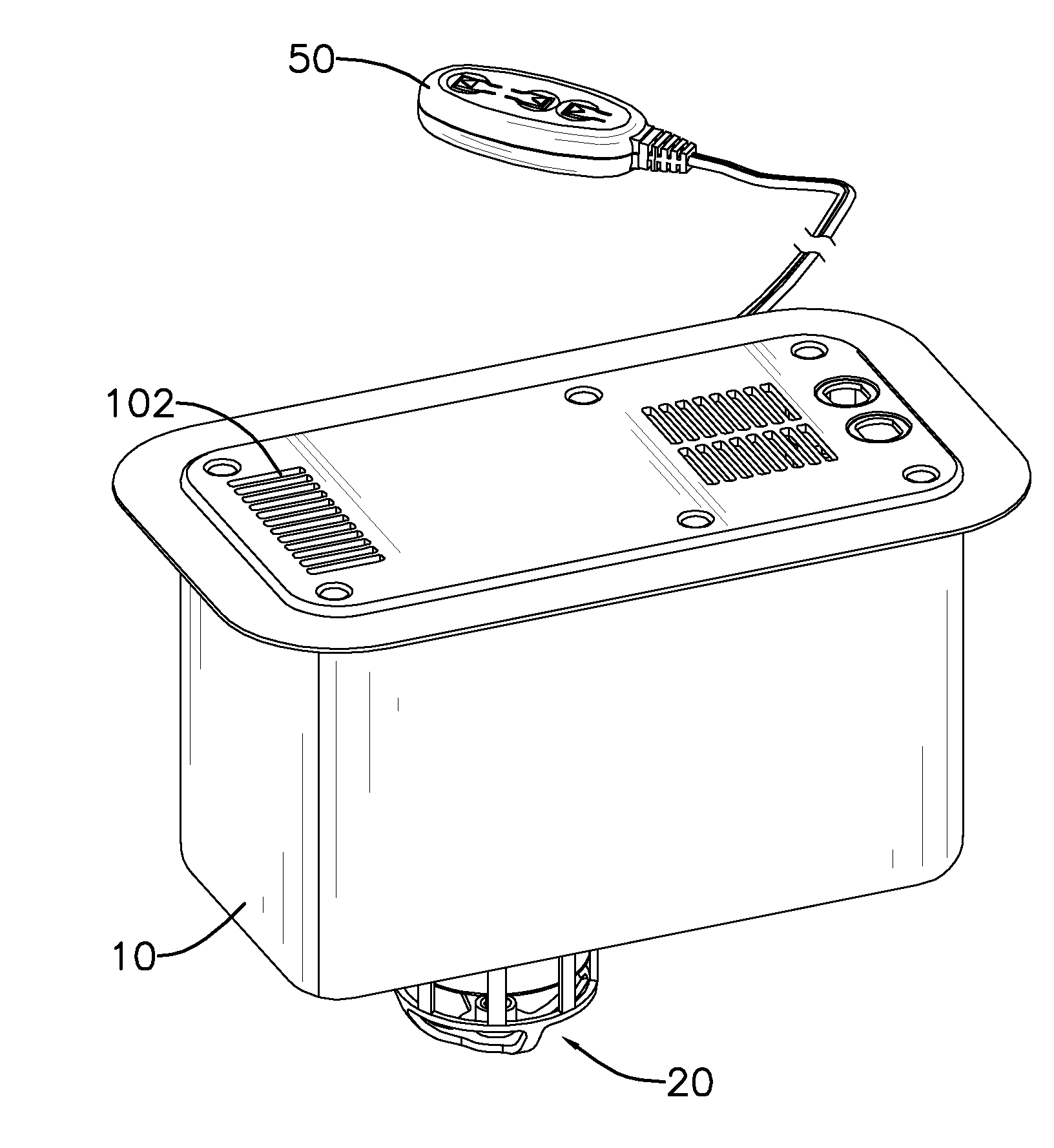
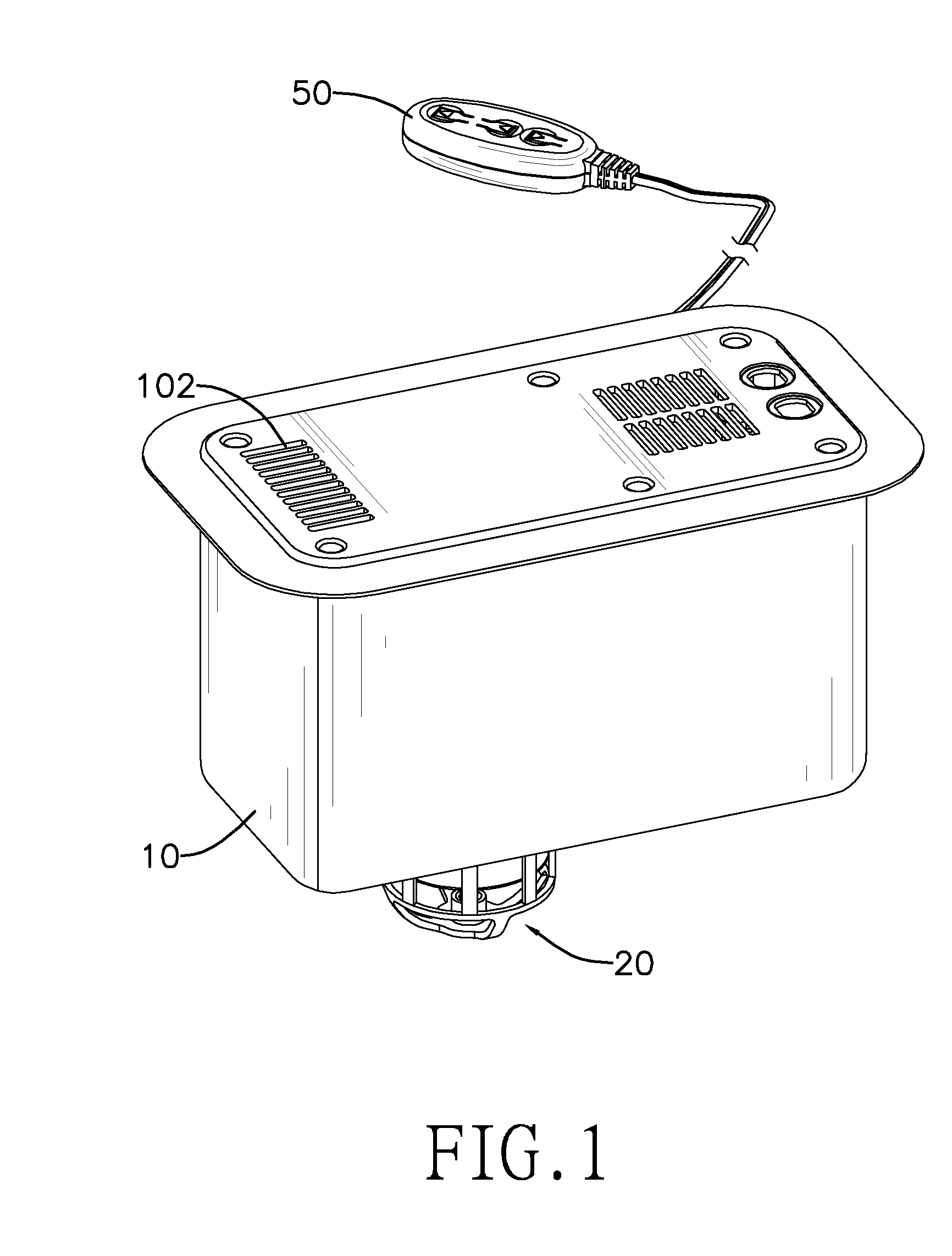
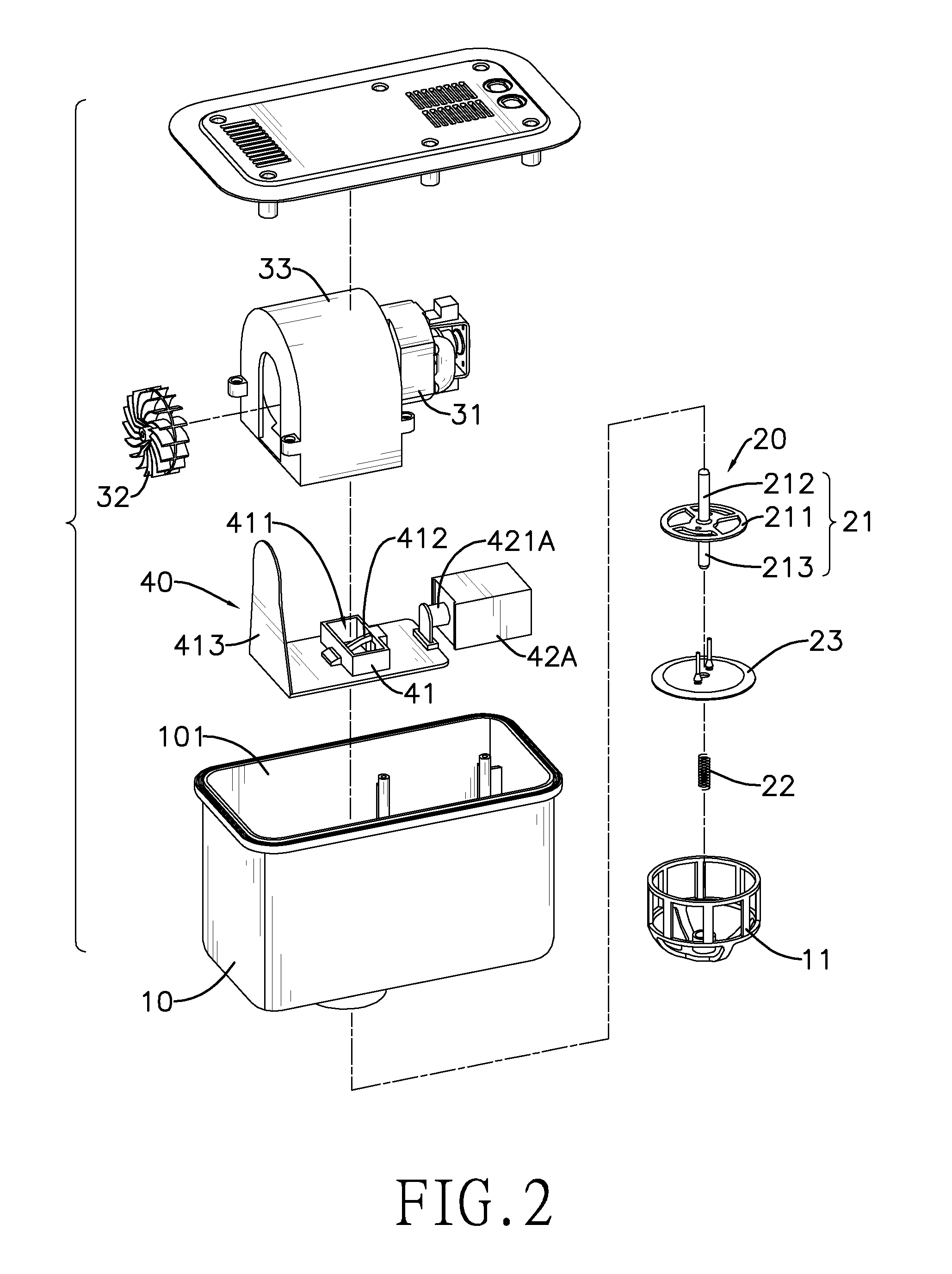
[0023]With reference to FIGS. 1 and 2, an air pump for an inflatable article in accordance with the present invention comprises a housing (10), a blower (30), a switch assembly (40) and an air valve (20) and may comprise a fan guard (11).

[0024]With further reference to FIG. 3, the housing (10) is mounted on the inflatable article and has an inner chamber (101), a first opening (102) and a second opening (103). The inner chamber (101) is defined in the housing (10). The first opening (102) is formed through a top of the housing (10), communicates with the inner chamber (101) of the housing (10) and is disposed outside the inflatable article. The second opening (103) is formed through a bottom of the housing (10), aligns with the first opening (102) of the housing (10), is disposed inside the inflatable article and communicates with the inner chamber (101) of the housing (10) and the inflatable article.

[0025]With further reference to FIGS. 4 and 5, the blower (30) is mounted in the in...


PUM


Abstract

An air pump for an inflatable article has a housing and a blower, a switch assembly and an air valve mounted in the housing. The switch assembly has a slider and a driving device sliding the slider and the air valve to switch operating modes of the air pump. Thus, the air pump inflates or deflates the inflatable article or maintains or fine-tunes the air pressure inside the inflatable article. Therefore, the first and second openings of the housing are disposed on the housing for connection to different kinds of inflatable articles and the airflow directly flows through the air pump so inflating and deflating the inflatable article is fast.

Description

BACKGROUND OF THE INVENTION[0001]1. Field of the Invention[0002]The present invention relates to an air pump for an inflatable article, especially to a compact air pump with rapid rate of inflation.[0003]2. Description of the Prior Art(s)[0004]Air pumps are connected to inflatable articles such as airbeds, inflatable trampolines, inflatable sofas, large-sized inflatable toys and the like and inflate or deflate the inflatable articles for use or storage.[0005]The conventional air pump for the inflatable article has a housing having an impeller, a motor, an electromagnetic valve, an air valve and a slider mounted in the housing. The housing has an inner hole formed through a sidewall of the housing and an outer hole formed through a bottom of the housing. The motor is connected to and rotates the impeller at high speed to create an airflow. The electromagnetic valve has a shaft. The air valve is connected to an end of the shaft of the electromagnetic valve and corresponds to the inner...

Claims


Application Information

Patent Timeline
IPC IPC(8): F04B17/00
CPCA47C27/082F04D27/009F04D25/08F04D29/503F04D25/084
Inventor TSAI, CHUN-CHUNG
Owner DONGGUAN TIGER POINT METAL & PLASTIC PRODS
Learn More