Intravascular photoacoustic and utrasound echo imaging

a technology of ultrasound echo imaging and ultrasound, applied in the field of photoacoustic imaging and ultrasound echo imaging, can solve the problems of inability to clinically demonstrate, limitations, and compromise image quality

Inactive Publication Date: 2011-01-27
BOARD OF RGT THE UNIV OF TEXAS SYST
View PDF21 Cites 79 Cited by
  • Summary
  • Abstract
  • Description
  • Claims
  • Application Information

AI Technical Summary

Benefits of technology

[0007]The invention relates generally to photoacoustic imaging and ultrasound echo imaging in combination. The invention enables the artisan to combine photoacoustic and ultrasound echo images acquired from vantage points within the lumen of an organ or vessel of a sub

Problems solved by technology

Optical coherence tomography (“OCT”) is a high resolution technique in principle but, in practice, the light-scattering inherent in it compromises image quality (Fujimoto, J. G. et al., “High resolution in vivo intra-arterial imaging with optical coherence tomography.”Heart 82: 128-133, 1999).
However, the ability of X-ray angiography to detect vulnerable plaques is minimal Ambrose, J. A. et al., “Angiographic progressi

Method used


Image

  • Intravascular photoacoustic and utrasound echo imaging
  • Intravascular photoacoustic and utrasound echo imaging
  • Intravascular photoacoustic and utrasound echo imaging

Examples


example 1

Design of One Embodiment of a Combined IVUS / IVPA Imaging System

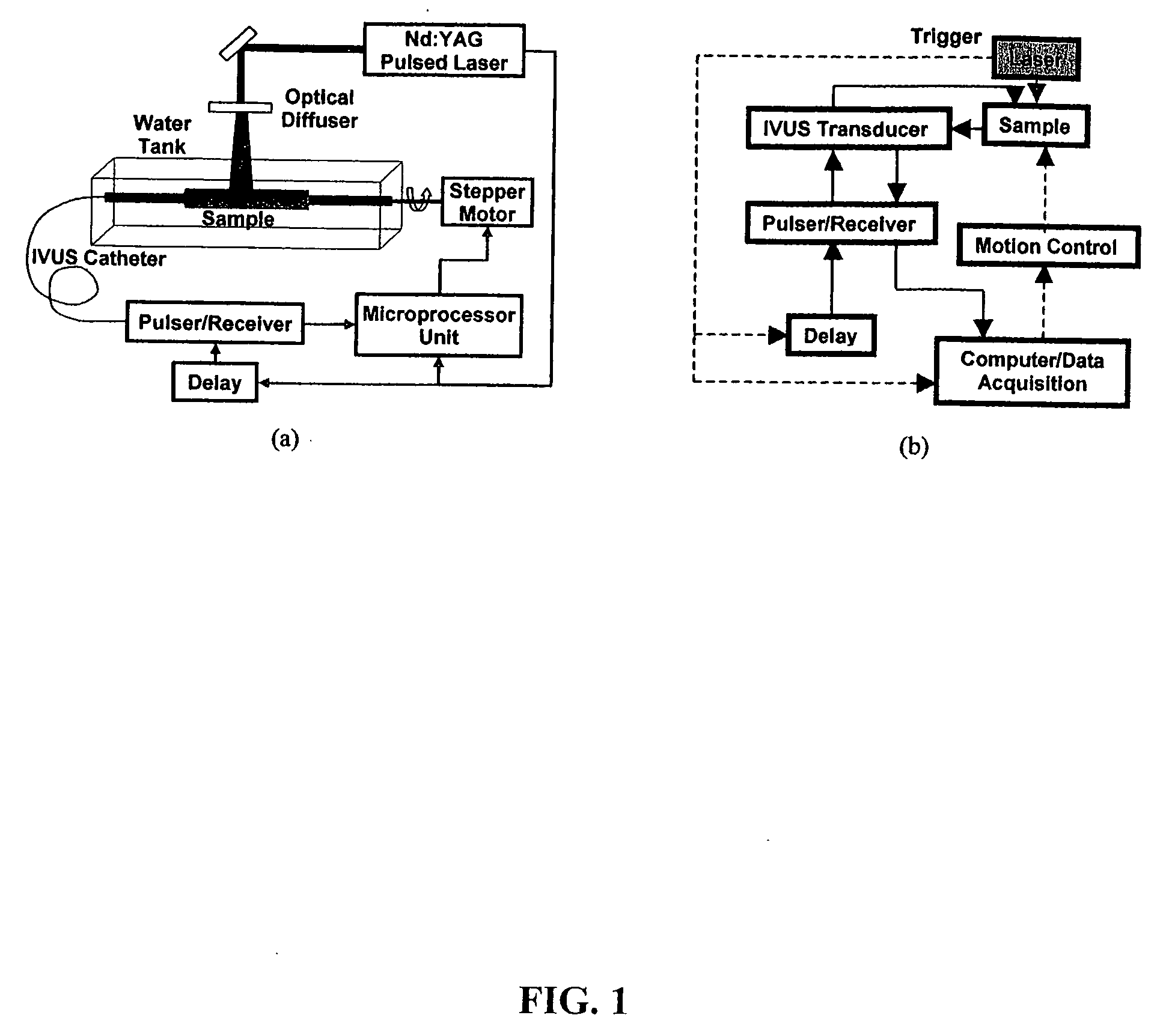
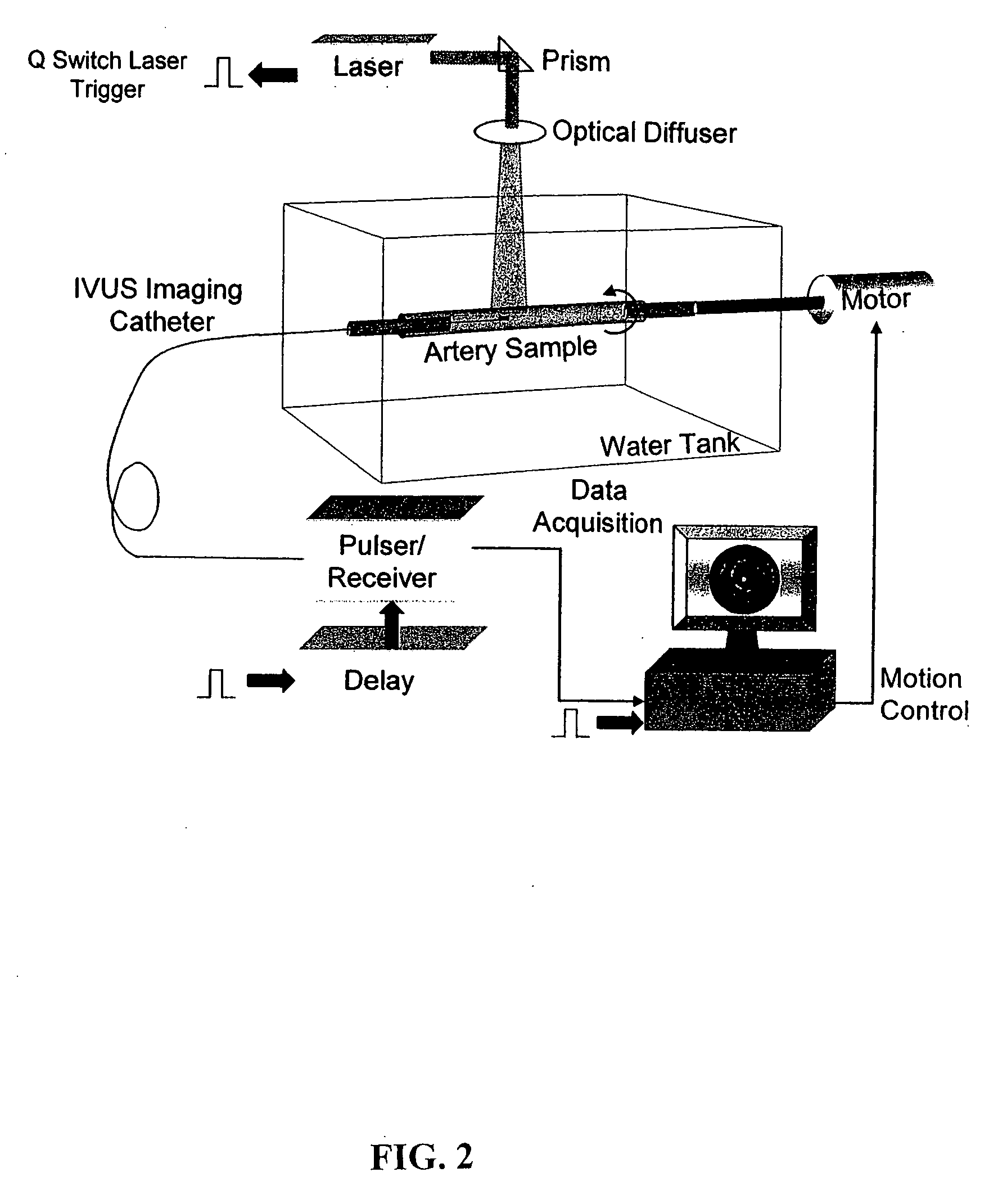
[0082]Various components of the combined imaging system were integrated to simultaneously acquire an IVUS and IVPA image. The main components of the IVUS / IVPA imaging system include an optical excitation module needed for photoacoustic imaging, a scanning and imaging module for obtaining co-registered IVUS and IVPA images, an ultrasound signal detection probe and associated electronic components. These components, as used in a laboratory experiment, are illustrated schematically in a FIG. 1a. A block diagram of the laboratory prototype of the combined IVUS / IVPA imaging system is presented in FIG. 1b. The prototype is illustrated more graphically in FIG. 2.

[0083]Generally, in photoacoustic imaging, the sample is irradiated with laser pulses of short pulse-width. Generally, pulses 3-10 ns long are used. Pulses of this length (in time) satisfy the acoustic confinement criterion. The selection of an appropriate excitation wa...

example 2

Intravascular Photoacoustic Imaging of Atherosclerotic Plaques: Ex Vivo Study Using a Rabbit Model of Atherosclerosis

[0096]In Example 1, intravascular photoacoustic (IVPA) imaging was demonstrated using the vessel phantom. Structures having distinct optical absorption characteristics were identified with good contrast in the IVPA images. The results also highlighted the ability of IVPA imaging to provide functional characteristics in addition to anatomical features exhibited by the intravascular ultrasound (IVUS) imaging. The initial IVPA images of the excised aorta samples show that photoacoustic signals can be obtained from highly scattering vessel wall structures. In this Example 2, we further investigated the ability of IVPA imaging to differentiate plaques through ex vivo studies on the aorta obtained from a rabbit model of atherosclerosis. In addition, we performed experiments to investigate the challenges associated with the in vivo implementation of IVPA imaging. Specificall...

example 3

Combined IVUS / IVPA Imaging In Vivo

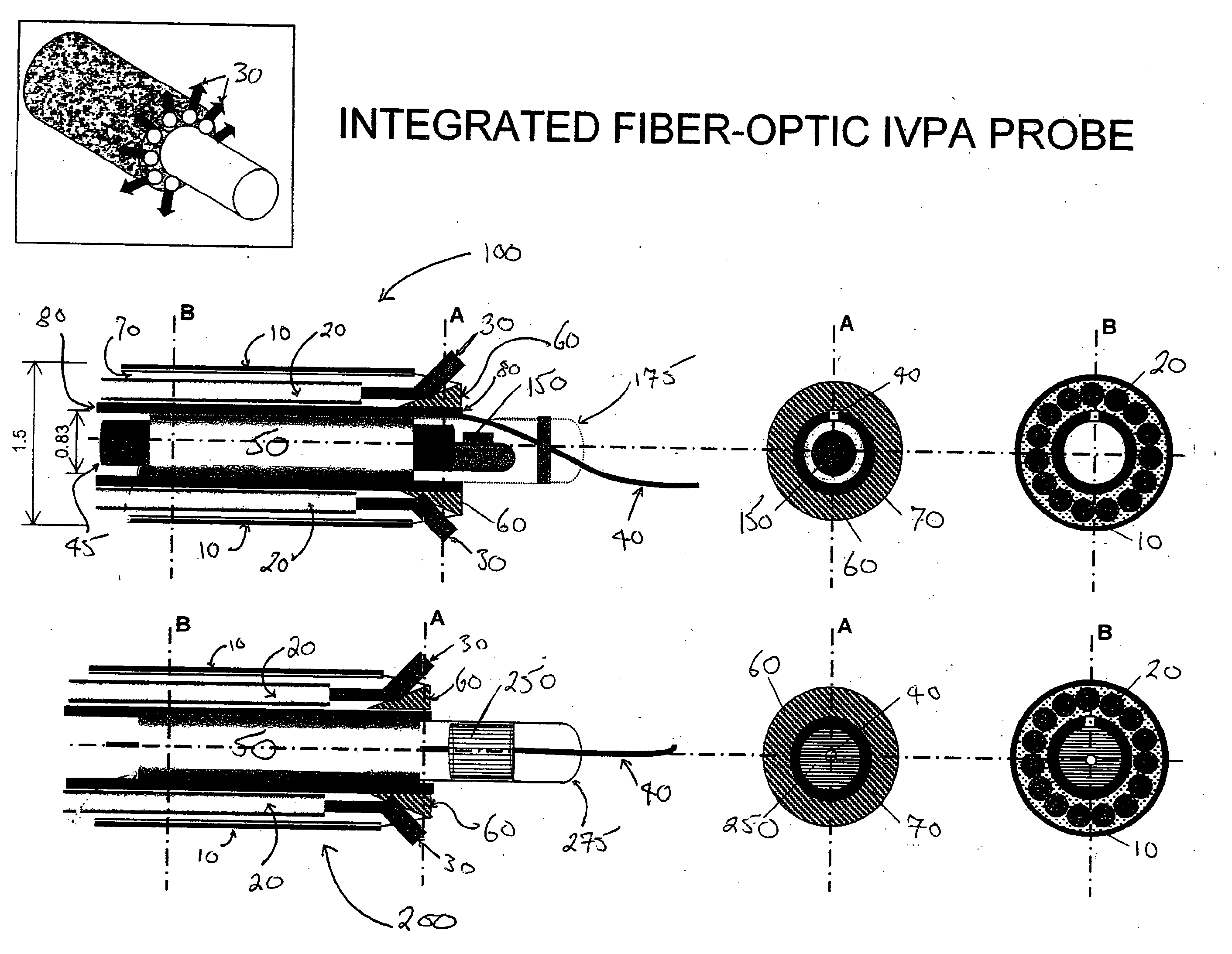
[0110]In this Example 3, an integrated IVUS / IVPA imaging catheter 100 suitable for clinical use is made by surrounding an IVUS catheter (iSight™ in the single-element device 175 in this example, the Avanar® F / X in the multielement device 275) with an array of optical fibers 20, which array is itself surrounded by an outer sheath 10 fabricated with a flexible plastic material to create a combination catheter 100. A copolymer of polyoxymethylene and polyurethane is exemplary (see U.S. Patent Publication 2003 / 0167051, incorporated herein in its entirety by reference for all purposes). The arrayed optical fiber bundles 20 are embedded or “potted” in a glue 70. The glue is capable of adhering to the material of the inner sheath 80, the outer sheath 10 and the outer surfaces of the fiberoptic bundles 20 and, after curing, has about the same degree of flexibility as these materials. Each fiber bundle 20 originates proximally at an interface with a laser li...


PUM


Abstract

The invention relates to photoacoustic imaging and ultrasound echo imaging In combination, and applies in particular to the field of imaging a lumen of an organ or vessel of a subject, wherein the Images are acquired from within a lumen of the organ or vessel, especially a lumen of a blood vessel to diagnose and treat vascular disease An exemplary embodiment of the invention is a catheter having an ultrasound transducer, the transducer comprising a probe suitable for generating and detecting photoacoustic signals and ultrasound echo signals, wherein the photoacoustic signals and the ultrasound echo signals are convertible to images which are integrated into an enriched image. The photoacoustic signals are generated by a multiplicity of energy sources suitable for inducing the walls of the blood vessel to generate acoustic waves, wherein the energy sources are arrayed in an annulus around the flexible tubular member.

Description

FIELD[0001]The invention relates generally to photoacoustic imaging and ultrasound echo imaging in combination, and applies in particular to the field of imaging the walls that define a lumen of an organ or vessel of a subject, wherein the images are acquired from a vantage point within a lumen of the organ or vessel, especially a lumen of a blood vessel to diagnose and treat vascular disease.BACKGROUND[0002]Cardiovascular disease (“CVD”) is the principal cause of mortality in the United States. The complications associated with CVD are primarily caused by atherosclerosis—a disease of the arteries. High levels of plasma low density lipoprotein cholesterol lead to the accumulation of lipids and to the formation of plaques deposited in the walls of the arteries (Ross, R., “The pathogenesis of atherosclerosis: a perspective for the 1990's,”Nature 362: 801-809, 1993). Plaque formation is further thought to be accompanied by an inflammatory response with the recruitment of monocyte-deriv...

Claims


Application Information

Patent Timeline
IPC IPC(8): A61B8/14A61B6/00
CPCA61B8/12A61B5/0095A61B5/0075A61B5/02007A61B5/6852A61B8/0891A61B8/14A61B8/445A61B8/4483A61B8/5207A61B8/5261
Inventor SETHURAMAN, SHRIRAMEMELIANOV, STANISLAV Y.SMALLING, RICHARD W.AGLYAMOV, SALAVAT R.
Owner BOARD OF RGT THE UNIV OF TEXAS SYST
Why Eureka
Try Eureka