Method and apparatus for effecting controlled restart of electrical servcie with a utility service area

a technology of electrical service and control apparatus, applied in the field of electric power generation and distribution systems, can solve problems such as system control errors, power outages, and unexpected excessive demand

Active Publication Date: 2011-01-27
JOSEPH W FORBES JR +1
View PDF99 Cites 84 Cited by
  • Summary
  • Abstract
  • Description
  • Claims
  • Application Information

AI Technical Summary

Problems solved by technology

In electric power systems, power outages occur for a variety of reasons.
However, most outages are unplanned and result from inclement weather, unexpected excessive demand, or system control errors.
In addition, brown-outs may occur when system load has been cut to offset or account for power quality or supply issues.
However, restoring power to many customers simultaneously or within a very short period of time can cause additional problems.
For example, power restoration after a planned or unplanned power outage often causes a momentary and sometimes harmful “spike” or surge in power on the utility grid from generation and distribution perspectives.
Atypical changes in demand may occur that are so abrupt that they cause a substantial fluctuation in line frequency within the utility's electric grid.
Thus, the regulating reserve component of a utility's operating reserve is typically limited to correcting for changes in line frequency.
Typically, when additional power is needed for use as economic dispatch, a power utility will make use of its spinning reserve before using its non-spinning reserve because the g

Method used


Image

  • Method and apparatus for effecting controlled restart of electrical servcie with a utility service area
  • Method and apparatus for effecting controlled restart of electrical servcie with a utility service area
  • Method and apparatus for effecting controlled restart of electrical servcie with a utility service area

Examples


Embodiment Construction

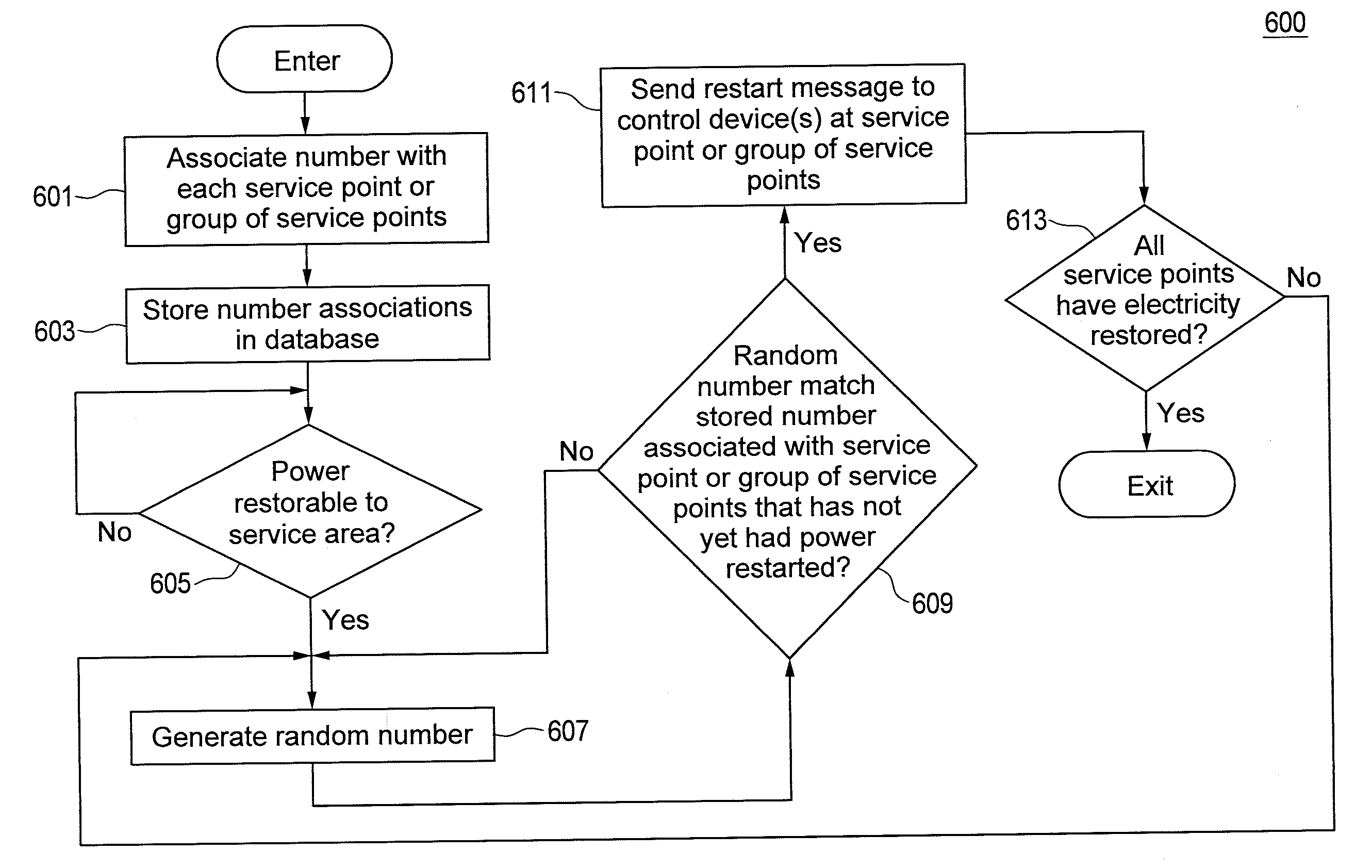
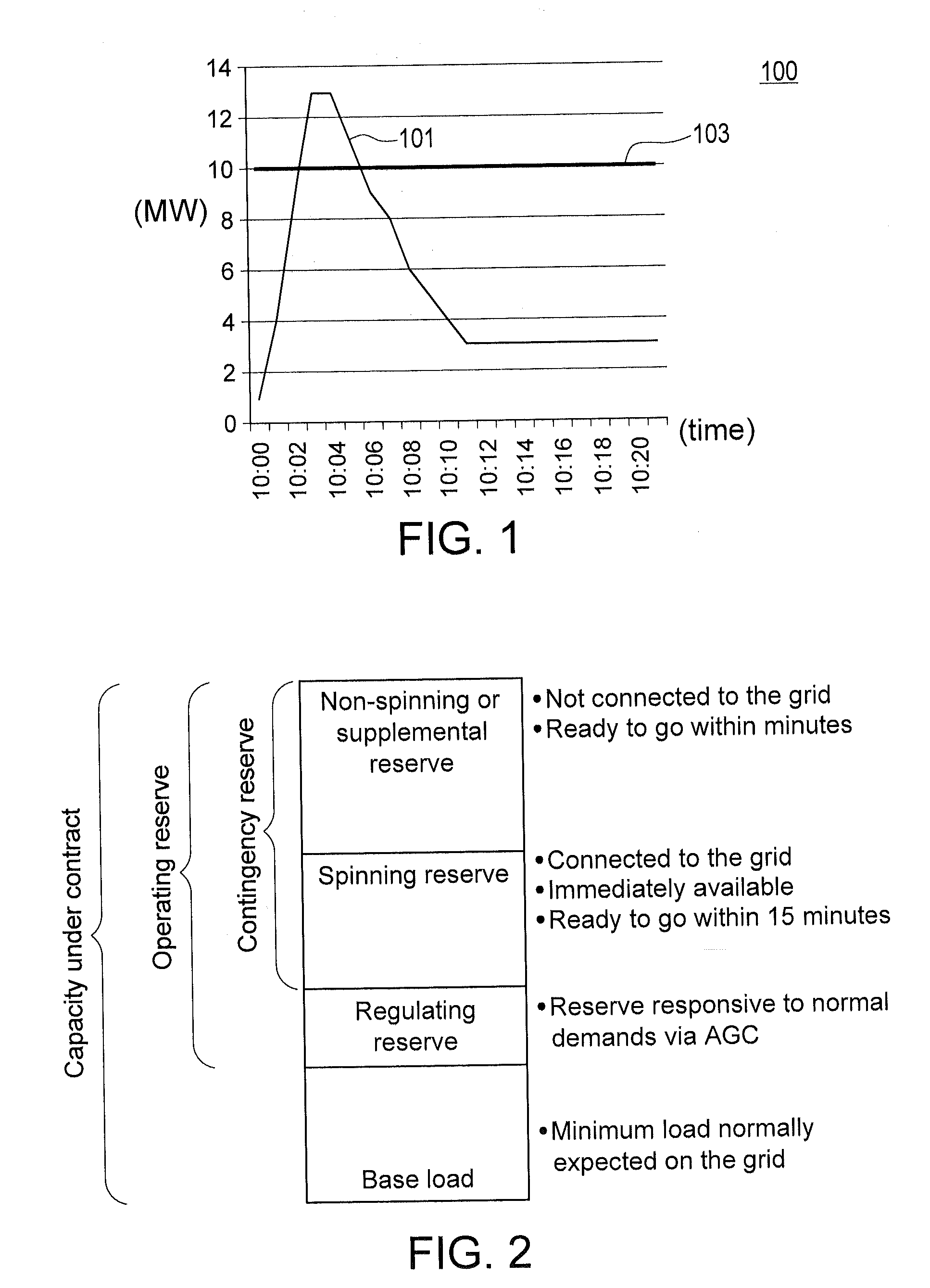
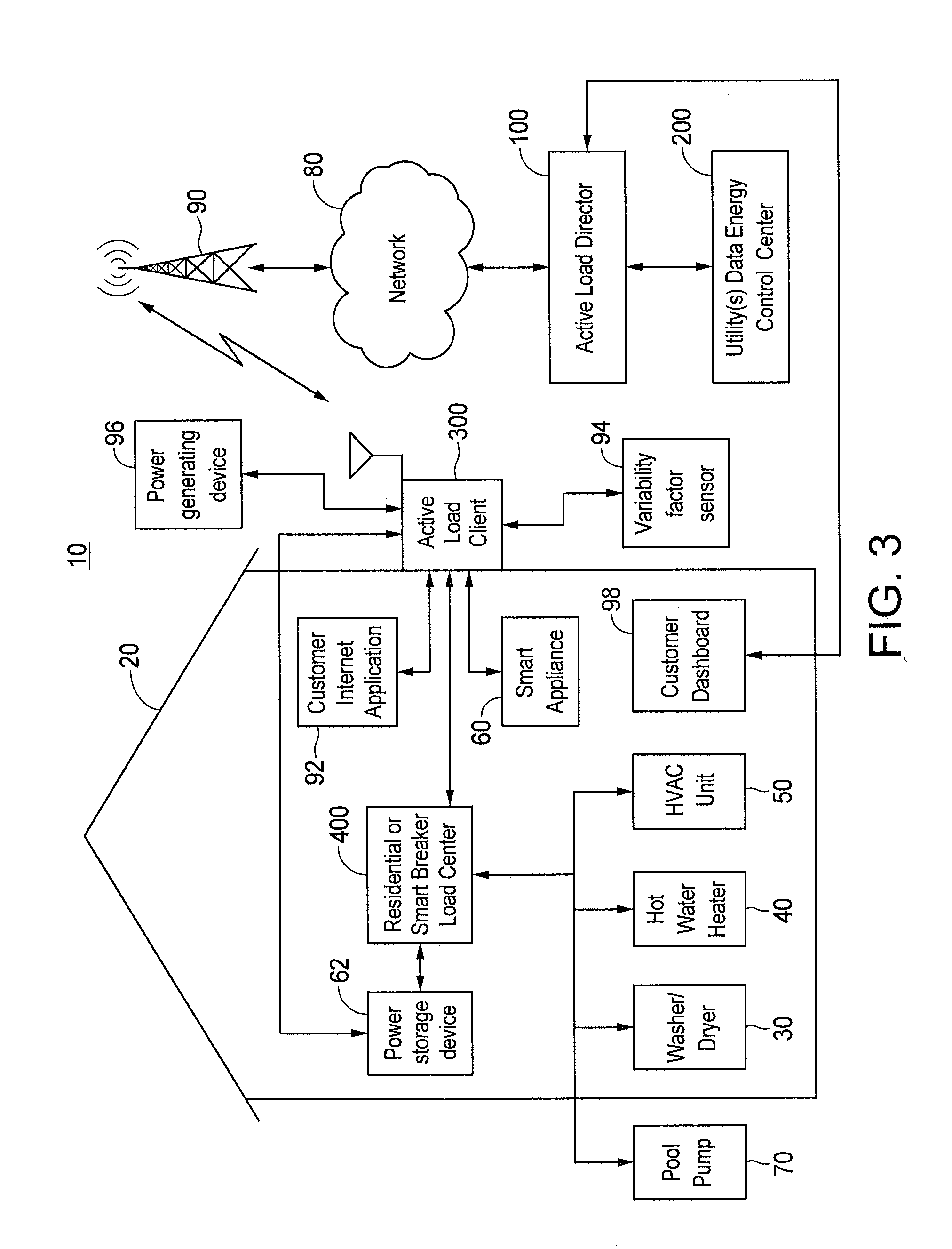
[0024]Before describing in detail exemplary embodiments that are in accordance with the present invention, it should be observed that the embodiments reside primarily in combinations of apparatus components and processing steps related to effecting a controlled restart of electrical service to service points within an electric utility's service area so as to mitigate the likelihood of a cold restart power spike without requiring use of the utility's contingency reserve. Accordingly, the apparatus and method components have been represented where appropriate by conventional symbols in the drawings, showing only those specific details that are pertinent to understanding the embodiments of the present invention so as not to obscure the disclosure with details that will be readily apparent to those of ordinary skill in the art having the benefit of the description herein.

[0025]In this document, relational terms, such as “first” and “second,”“top” and “bottom,” and the like, may be used ...


PUM

PropertyMeasurementUnit
Timeaaaaaaaaaa
Poweraaaaaaaaaa
Power consumptionaaaaaaaaaa

Abstract

An active load management system (ALMS) controllably restarts electrical service to service points in a utility service area after a power outage. The ALMS includes client devices installed at the service points and a central controller. In one embodiment, the controller associates numbers with the service points and stores the associations. Each service point may be associated with a unique number or a group of service points may share a number. After receiving notification that power is available, the controller determines a number and communicates the number to one or more of the client devices. Where the number was determined randomly, the client devices associated with the number may restart electrical service upon receipt of the number. Where the number was determined sequentially, a client device may determine its own random number and compare it to the received number. If a match occurs, electrical service can be restarted.

Description

CROSS REFERENCE TO RELATED APPLICATIONS[0001]This application is a continuation-in-part of U.S. application Ser. No. 12 / 715,124 filed on Mar. 1, 2010, which is a division of U.S. application Ser. No. 11 / 895,909 filed on Aug. 28, 2007, now U.S. Pat. No. 7,715,951 B2, and is incorporated herein by this reference as if fully set forth herein. This application is also a continuation-in-part of U.S. application Ser. No. 12 / 715,195 filed on Mar. 1, 2010, which is also a division of U.S. application Ser. No. 11 / 895,909, now U.S. Pat. No. 7,715,951 B2, and is incorporated herein by this reference as if fully set forth herein. This application is further a continuation-in-part of U.S. application Ser. No. 12 / 702,640 filed on Feb. 9, 2010, which is a continuation-in-part of U.S. application Ser. No. 11 / 895,909, now U.S. Pat. No. 7,715,951 B2, claims priority upon U.S. Provisional Application No. 61 / 150,978 filed on Feb. 9, 2009 and U.S. Provisional Application No. 61 / 176,752 filed on May 8, 2...

Claims


Application Information

Patent Timeline
IPC IPC(8): G05D3/12
CPCG06Q10/00H02J9/04
Inventor FORBES, JR., JOSEPH W.WEBB, JOEL L.
Owner JOSEPH W FORBES JR
Why Eureka
Try Eureka