Vehicular manipulation input apparatus

a technology of input apparatus and input, which is applied in the direction of dashboard fitting arrangement, navigation instruments, instruments, etc., can solve the problems of input being executed by unintentional touching, input being incorrectly manipulated, and causing mismanipulation

Inactive Publication Date: 2011-02-03
DENSO CORP
View PDF12 Cites 79 Cited by
  • Summary
  • Abstract
  • Description
  • Claims
  • Application Information

AI Technical Summary

Benefits of technology

[0007]It is an object of the present invention to provide a vehicular manipulation

Problems solved by technology

The remote manipulation section of the above manipulation input apparatus is arranged at the reach of the use's hand, thus posing a problem that the manipulation section is touched without user's intention, thereby causing an incorrect manipulation input.
In particular, in case that the manipulation section is a touch manipulation type such as a touch pan

Method used


Image

  • Vehicular manipulation input apparatus
  • Vehicular manipulation input apparatus
  • Vehicular manipulation input apparatus

Examples


first embodiment

1. First Embodiment

1.1 First Example

[0089]Hereinafter, the first example of a manipulation input apparatus according to the first embodiment of the present invention is explained with reference to the drawings.

[0090](Configuration)

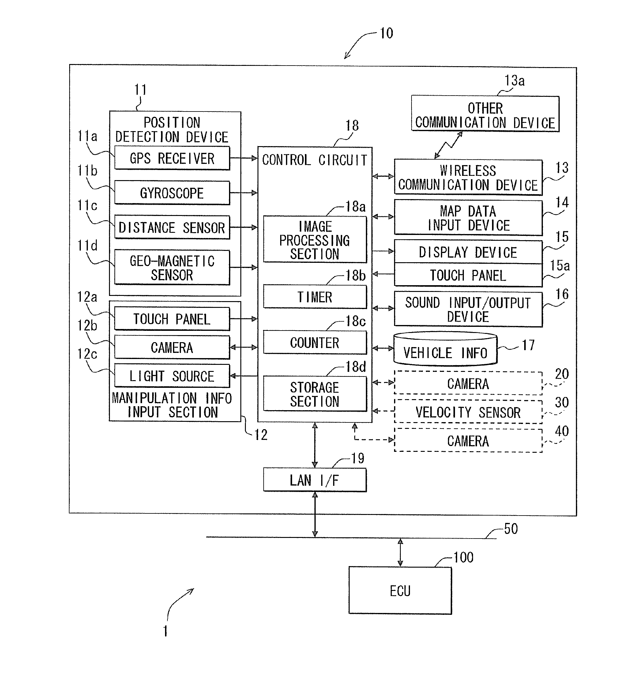
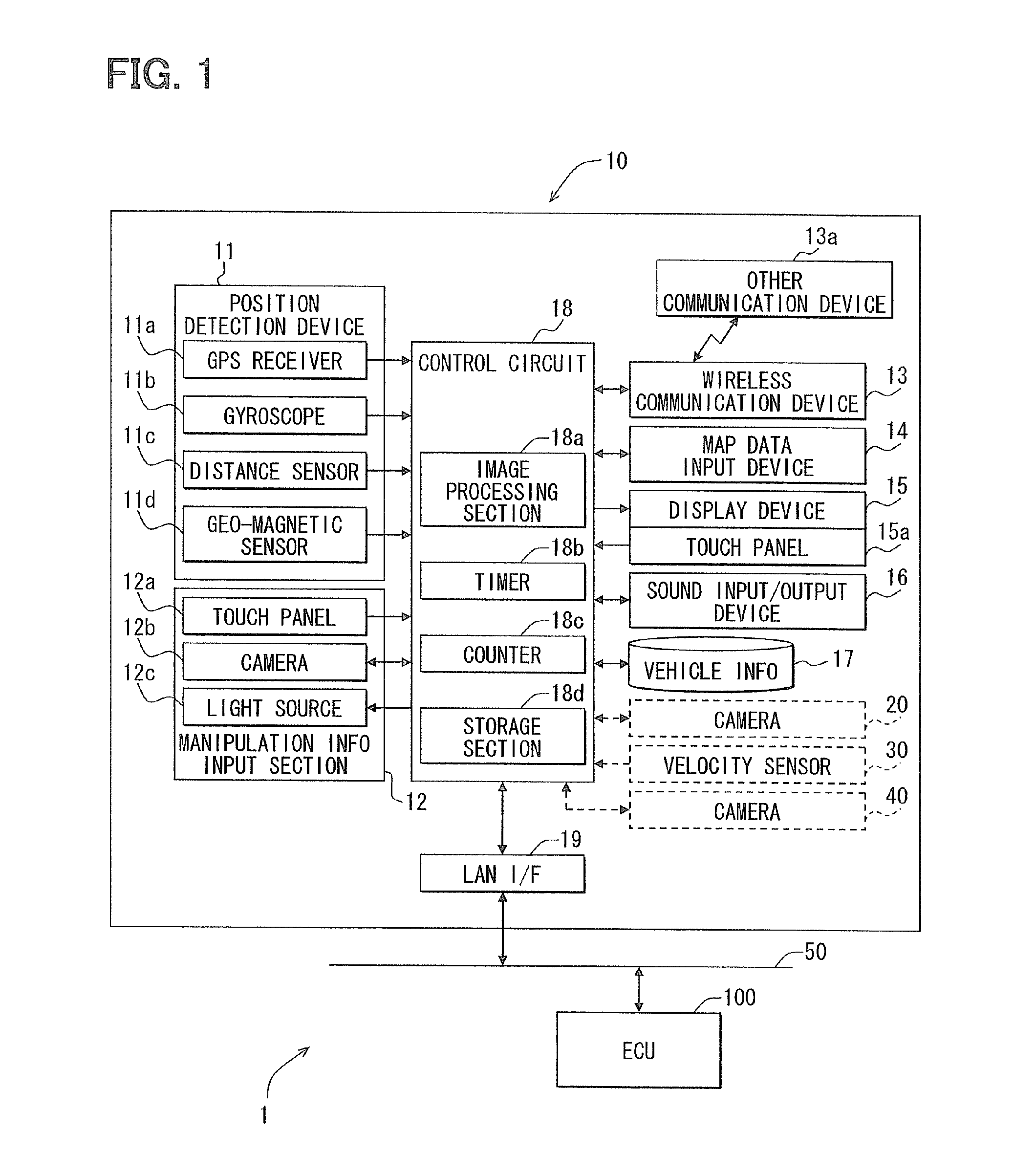
[0091]FIG. 1 is a block diagram illustrating a configuration of a vehicular navigation apparatus using a manipulation input apparatus of the present embodiment. Under the present example, in the manipulation input apparatus 1, a display device 15 and a manipulation panel 12a are arranged respectively at different positions. The display device 15 can display an image for manipulation inputs, such as a switch image for touch manipulation (manipulation icon), on a display window. The manipulation panel 12a is used for executing touch manipulation to the display window remotely. It is noted that the touch type manipulation input apparatus of the present example can operate, as an operation target, not only the navigation function, but also functions of other i...

second example

1.2 Second Example

[0141]The following explains the second example of the present embodiment.

[0142]The first example is configured as follows. When the simple manipulation-use finger state is specified as the predetermined finger state, the display permission mode is assigned which permits the display of the position indication image; when the simple manipulation-use finger state is not specified, the display prohibition mode is assigned which prohibits the display of the position indication image. Such display mode switchover control may be configured as follows. When the vehicle is in a predetermined travel state, the control is made. When it is not in the predetermined travel state, the display permission mode is assigned to the display mode. In such cases, a vehicle travel state detection section or means need to be included. FIG. 11 shows an example of such a process. Herein, the configuration includes a vehicle velocity sensor 30 (vehicle velocity detection section or means) wh...

second embodiment

2. Second Embodiment

2.1 First Example

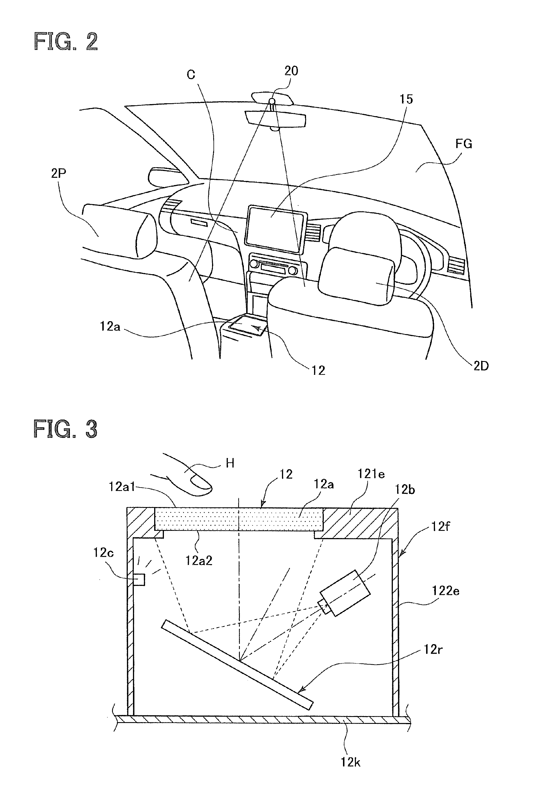
[0291]Hereinafter, the first example of a manipulation input apparatus according to the second embodiment of the present invention is explained with reference to the drawings. The explanation of the second embodiment is mainly made to focus on the difference from the first embodiment while omitting the same as the first embodiment. (Configuration) A configuration of a vehicular navigation apparatus using a manipulation input apparatus of the second embodiment is mainly illustrated in FIG. 1, FIG. 3, and FIG. 69 of the first embodiment. That is, FIG. 69 does not include a camera 20 shown in FIG. 2. Others are almost the same.

[0292]FIGS. 4 to 7 are drawings for explaining image captures of a hand (finger) H which opposes the manipulation panel 12a. Although the window display shown in FIG. 4 (c) is not executed in the first embodiment, the window display shown in FIG. 4 (c) may be executed in the second embodiment.

[0293](Display Process of Position...


PUM


Abstract

A vehicular manipulation input apparatus for a vehicle includes a manipulation panel, and a display device which displays a position indication image for displaying an indication position on the manipulation panel. It is specified whether a finger state of a hand opposing the manipulation panel is a manipulation intention expression-use finger state. In a condition that the vehicle is in a travel state, a display of the position indication image is permitted when the finger state is specified as the manipulation intention expression-use finger state whereas a display of the position indication image is prohibited when the finger state is not specified as the manipulation intention expression-use finger state.

Description

CROSS REFERENCE TO RELATED APPLICATION[0001]The present application is based on and incorporates herein by reference Japanese Patent Application No. 2008-71467 filed on Mar. 19, 2008, Japanese Patent Application No. 2008-71468 filed on Mar. 19, 2008, Japanese Patent Application No. 2008-71470 filed on Mar. 19, 2008, Japanese Patent Application No. 2008-291592 filed on Nov. 14, 2008, Japanese Patent Application No. 2009-21003 filed on Jan. 30, 2009, Japanese Patent Application No. 2009-21004 filed on Jan. 30, 2009, and Japanese Patent Application No. 2009-21005 filed on Jan. 30, 2009.TECHNICAL FIELD[0002]The present invention relates to a vehicular manipulation input apparatus.BACKGROUND ART[0003][Patent document 1] JP-2000-6687 A[0004]In recent years, there is developed a manipulation input apparatus, which manipulates a device remotely, such as a prompter-type manipulation input apparatus (Patent document 1). In such a manipulation input apparatus, separately of a display device to...

Claims


Application Information

Patent Timeline
IPC IPC(8): G06F19/00G06F3/041
CPCB60K37/06G06F3/0488B60K2350/2004B60K2350/906B60R11/0235B60R2001/1253B60R2011/0007G01C21/3664G06F3/017G06F3/0304G06F3/0312G06F3/0425G06F3/0426G06F3/0428B60K2350/1012B60K2370/141B60K2370/1537B60K2370/195B60K35/00B60R16/02G06F3/00
Inventor AOKI, TAKASHIAKAHORI, ICHIRONIWA, SHINJIITOH, MASAHIROKAWASHIMA, TAKESHINAGATA, TAKASHI
Owner DENSO CORP
Why Eureka
Try Eureka