Micromachined inertial sensor devices

Active Publication Date: 2011-02-10
SEMICON COMPONENTS IND LLC
View PDF100 Cites 152 Cited by
  • Summary
  • Abstract
  • Description
  • Claims
  • Application Information

AI Technical Summary

Problems solved by technology

However, majority of the existing MEMS sensors measure either acceleration or rotation, but not the 6 degrees-of-freedom (three independent accelerations and three independe

Method used


Image

  • Micromachined inertial sensor devices
  • Micromachined inertial sensor devices
  • Micromachined inertial sensor devices

Examples


Embodiment Construction

[0021]The following detailed description is of the best currently contemplated modes of carrying out the invention. The description is not to be taken in a limiting sense, but is made merely for the purpose of illustrating the general principles of the invention because the scope of the invention is best defined by the appended claims.

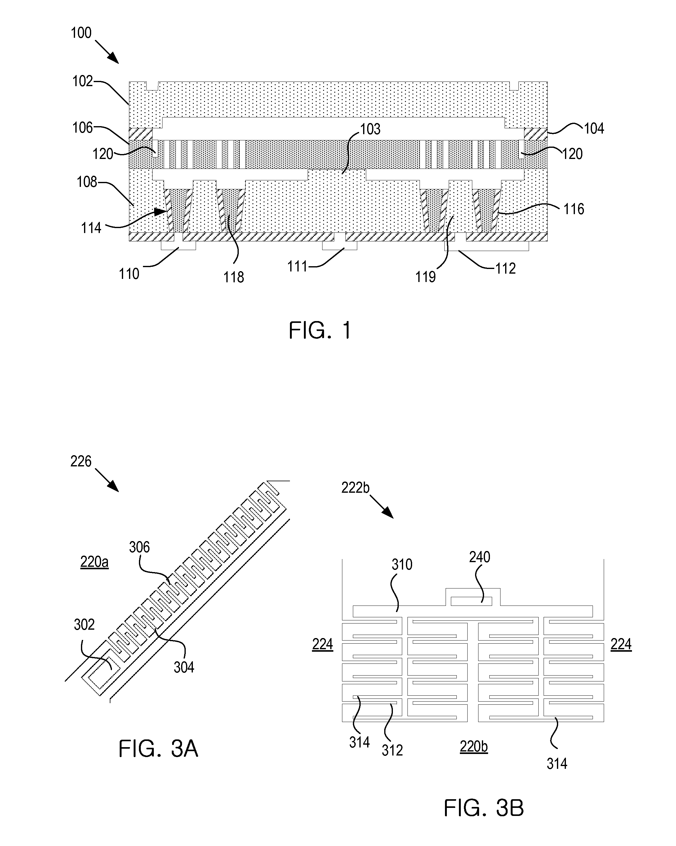
[0022]FIG. 1 shows a schematic cross sectional view of a multi-DOF device 100. As depicted, the multi-DOF device 100 includes a cap wafer 102; a device layer (or, equivalently, MEMS layer or micromachined structure layer) 106 that includes micromachined structures (or, MEMS structures); and a via wafer 108. The cap wafer 102 may be metal bonded to the device layer 106, where the metal bonding 104 can generate thermal stress between the cap wafer 102 and the device layer 106 during operation. To isolate the micromachined structures from the thermal stress, a stress reducing groove 120 can be formed around the perimeter of the device layer 106. The metal...


PUM


Abstract

A micromachined inertial sensor with a single proof-mass for measuring 6-degree-of-motions. The single proof-mass includes a frame, an x-axis proof mass section attached to the frame by a first flexure, and a y-axis proof mass section attached to the frame by a second flexure. The single proof-mass is formed in a micromachined structural layer and is adapted to measure angular rates about three axes with a single drive motion and linear accelerations about the three axes.

Description

CROSS REFERENCE TO RELATED APPLICATIONS[0001]This application claims the benefit of U.S. Provisional Applications No. 61 / 273,538, entitled “Performance enhancements and fabrication method of micromachined integrated 6-axis inertial measurement device,” filed on Aug. 4, 2009, and 61 / 273,494, entitled “Micromachined inertial sensor devices and methods for making same,” filed on Aug. 4, 2009, which are hereby incorporated herein by reference in their entirety.BACKGROUND OF THE INVENTION[0002]The present invention generally relates to inertial sensor devices and, more particularly, to micromachined inertial sensor devices.[0003]With the rapid advance of modern electronic technology, various electronic devices, such as navigation systems, cell phones, and electronic games, require sensors that can accurately determine motions of the devices at low cost with small form factor. Conventional techniques have been developed to bump micro-electromechanical-systems (MEMS) chips on ASIC wafers o...

Claims


Application Information

Patent Timeline
IPC IPC(8): G01C19/56
CPCG01C19/5712G01P15/125G01P2015/0842G01P2015/082G01P15/18H01L2224/48091H01L2924/00014
Inventor ACAR, CENK
Owner SEMICON COMPONENTS IND LLC
Why Eureka
Try Eureka