MEMS teeter-totter accelerometer having reduced non-linearty

a technology of accelerometer and teeter-to-tter, applied in the field of accelerometers, can solve the problems of difficult linear output, significant obstacles in the design of micro-machined mems accelerometers,

Active Publication Date: 2006-11-28
HONEYWELL INT INC
View PDF32 Cites 57 Cited by
  • Summary
  • Abstract
  • Description
  • Claims
  • Application Information

AI Technical Summary

Benefits of technology

[0006]The present invention is an apparatus and method for fabricating a MEMS accelerometer device that overcomes limitations of the prior art by providing a pendulous out-of-plane accelerometer having cooperative moveable and stationary comb teeth arranged for symmetric operation about the actual rotational center of the proof mass, whereby non-linearity is substantially eliminated from the acceleration detection systems and the acceleration sensing is provided by linear detection.
[0007]Capacitive-sensing MEMS accelerometer designs are extremely popular for operation in high-g environments and for their low cost. The small overall geometry of these devices is ideal for high-g packages that require minimum size. However, even with their small size, reducing non-linearity effect causes in capacitive-sensing MEMS accelerometers is highly desirable. Reduction in non-linearity effect causes results in increased accuracy of mathematical models and corresponding coefficients, without a corresponding significant increase in the level of mathematical modeling beyond a second order equation.
[0008]The present invention mounts comb tooth sensors at extreme ends and sides of the pendulous mechanism structure. These comb tooth sensors are spaced symmetrically about the computed actual center of rotation, which results in excellent differential symmetry.
[0010]According to one aspect of the invention, positioning of pick-off comb teeth symmetrically at the extreme sides and ends of the proof mass positions the pick-off comb teeth for excellent differential signal detection by positioning the pick-off comb teeth within the portions of the proof mass that experience the greatest displacement when exposed to an acceleration or other force field during operation.

Problems solved by technology

Obtaining data from accelerometer output that has reduced non-linearity characteristics imposes significant obstacles for designs of micro-machined MEMS accelerometers.
In out-of-plane accelerometers that rely upon stacked parallel capacitor plates for detection by capacitive pick-off, obtaining linear output has been difficult because the capacitance varies inversely with displacement of the out-of-plane pendulous proof mass by 1 / d, where d is the distance between the capacitor plates on the pendulous proof mass and a relatively stationary frame from which the pendulous proof mass is suspended.

Method used


Image

  • MEMS teeter-totter accelerometer having reduced non-linearty
  • MEMS teeter-totter accelerometer having reduced non-linearty
  • MEMS teeter-totter accelerometer having reduced non-linearty

Examples


Embodiment Construction

[0016]In the Figures, like numerals indicate like elements.

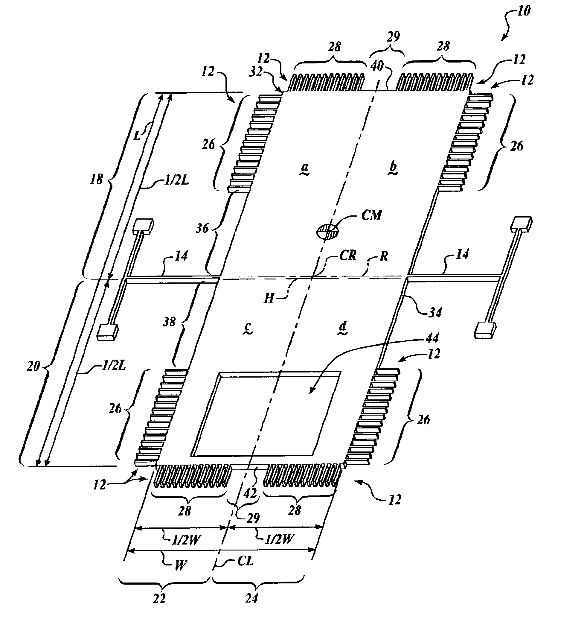
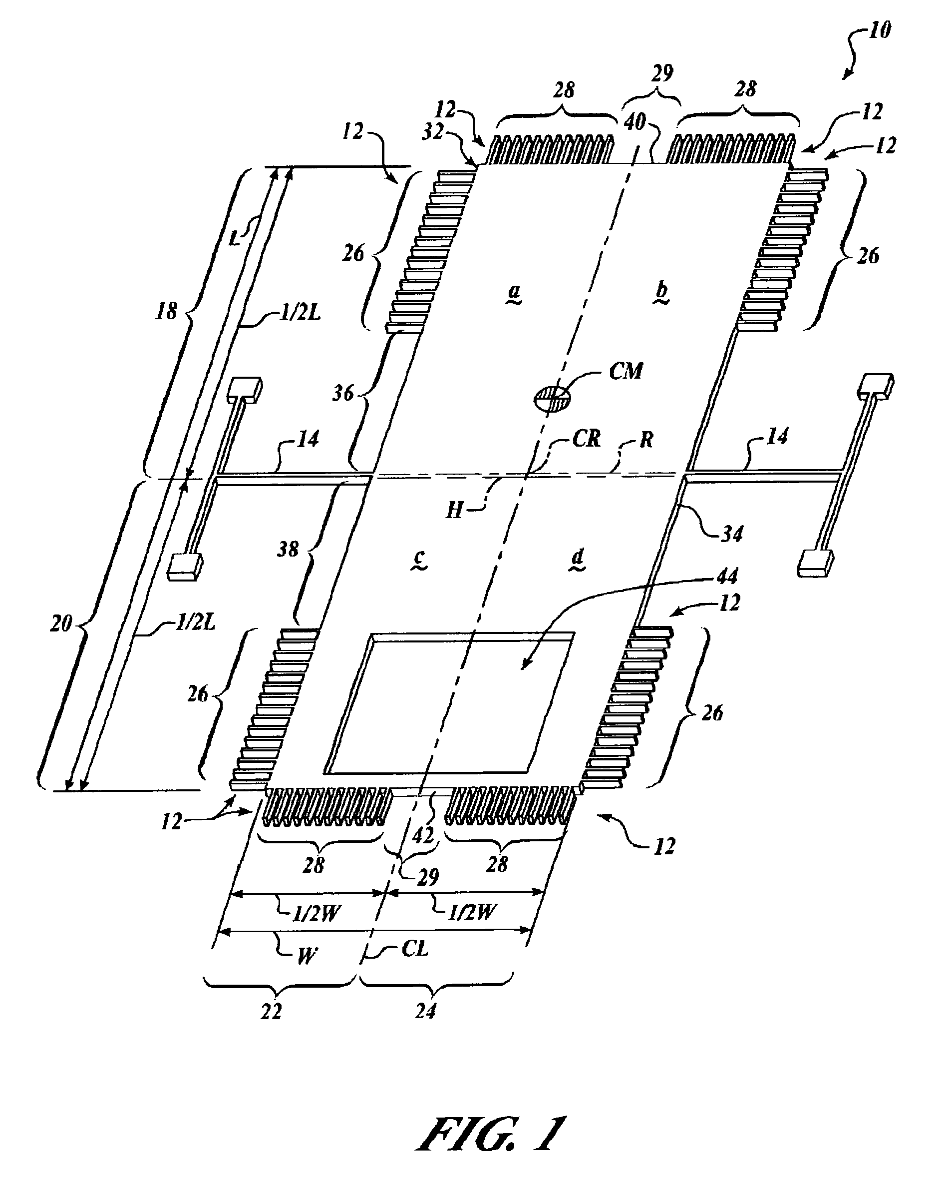
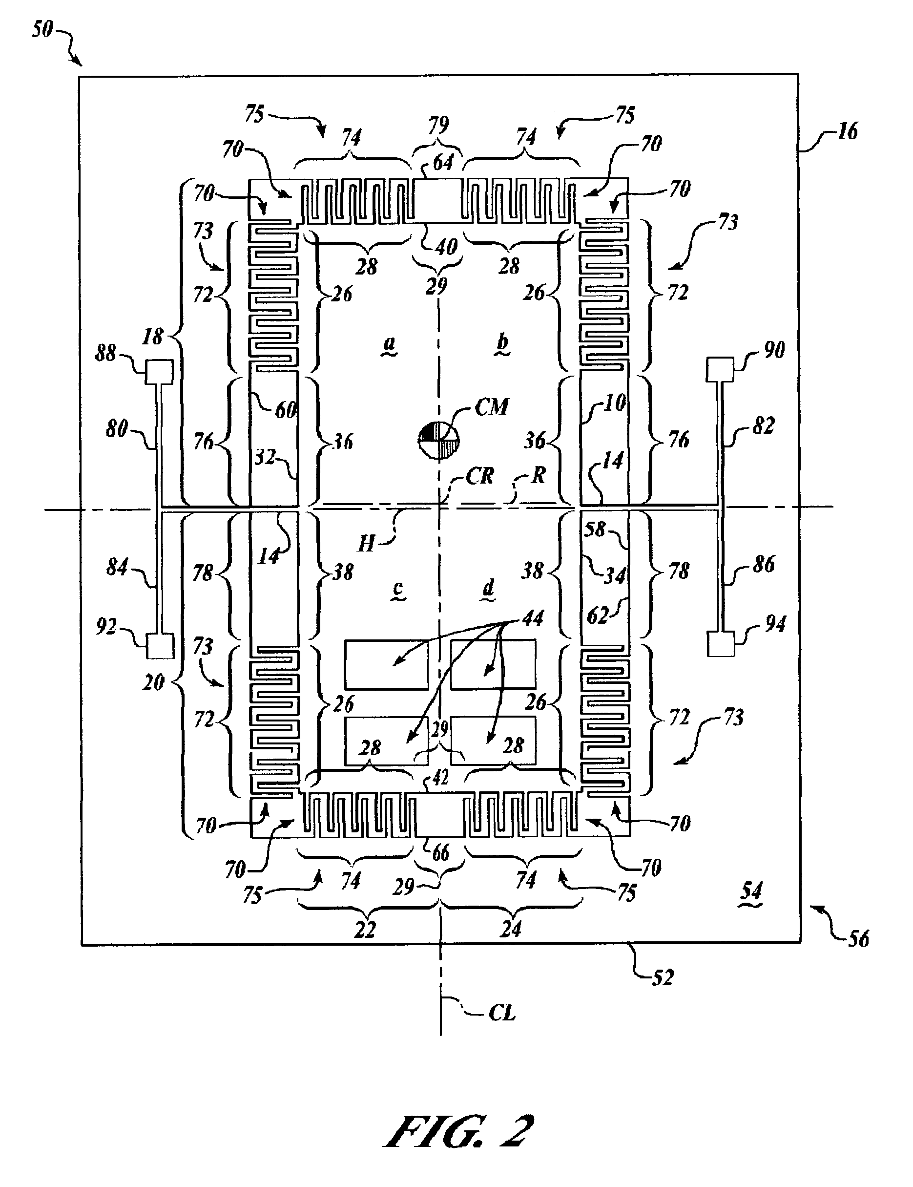
[0017]The Figures illustrate the accelerometer or other force sensing devices of the present invention, and methods for forming and assembling the same, by providing a substantially rectangular pendulous mechanism proof mass structure having multiple capacitive comb tooth sensors spaced symmetrically about an actual computed center of rotation thereof, with the multiple comb tooth sensors primarily at extreme side and end portions of the proof mass, which positions the pick-off comb teeth for substantially symmetrical differential signal detection within the portions of the proof mass that experience the greatest displacement when exposed to an acceleration or other force field during operation.

[0018]Additionally, a large portion of material is removed from the proof mass on one side of its axis of rotation, which maximizes pendulosity while maintaining symmetry of the differential signal detection.

[0019]FIG. 1 illustrates t...


PUM


Abstract

An apparatus and method for force sensing device having a pendulous mechanism proof mass formed in a silicon semiconductor substrate and structured for rotation about an intermediate rotational axis, the proof mass being substantially rectangular in shape with opposing first and second lateral peripheral edges and opposing first and second endwise peripheral edges. A plurality of capacitor comb teeth are formed symmetrically along the opposing first and second endwise peripheral proof mass edges and along the opposing first and second lateral peripheral proof mass edges adjacent to the first and second endwise peripheral edges, and one or more mass reduction apertures are formed in an interior portion of the proof mass on one side of the intermediate hinge axis.

Description

RELATED APPLICATIONS[0001]This application claims the benefit of U.S. Provisional Application Ser. No. 60 / 654,358, filed in the names of Ronald B. Leonardson and David L. Malametz on Feb. 18, 2005, the complete disclosure of which is incorporated herein by reference.FIELD OF THE INVENTION[0002]The present invention relates to accelerometers and other force sensing devices and methods of forming and assembling the same, and in particular, MEMS electrostatic comb-drive capacitive accelerometers.BACKGROUND OF THE INVENTION[0003]MEMS is a popular acronym for Micro-Electro Mechanical Systems, of which monolithic silicon based accelerometers are a subset, of which vibration beam detection accelerometers are a further subset. MEMS vibration beam detection accelerometer devices are generally well-known.[0004]Obtaining data from accelerometer output that has reduced non-linearity characteristics imposes significant obstacles for designs of micro-machined MEMS accelerometers. In out-of-plane ...

Claims


Application Information

Patent Timeline
Patent Type & Authority Patents(United States)
IPC IPC(8): G01P15/02G01C19/00G01P15/125
CPCG01P15/125G01P2015/0831
Inventor LEONARDSON, RONALD B.MALAMETZ, DAVID L.
Owner HONEYWELL INT INC
Why Eureka
Try Eureka