Methods and systems for controlling movement within MEMS structures

a technology of mems and structure, applied in the field of microelectromechanical systems, can solve problems such as undesired oscillations, and achieve the effect of reducing undesired oscillations of proof masses

Inactive Publication Date: 2005-03-01
HONEYWELL INT INC
View PDF27 Cites 55 Cited by
  • Summary
  • Abstract
  • Description
  • Claims
  • Application Information

AI Technical Summary

Benefits of technology

In one aspect, a method for reducing undesired movements of proof masses in micro-electromechanical systems (MEMS) devices is provided. The proof masses are suspended above a substrate by one or more suspensions. The method comprises providing an anchor on the substrate substantially between a first proof mass and suspensions for the first proof mass and a second proof mass and suspensions for the second proof mass. The method further comprises coupling a first portion of a beam to the first proof mass, coupling a second portion of the beam to the second proof mass, and attaching a third portion of the beam to the anchor, the third portion extending between the first portion and second portion of the beam, the anchor and the third portion configured to allow at least a partial rotation of the third portion of the beam about an axis perpendicular to the substrate.

Problems solved by technology

These other oscillations are undesired and typically occur at frequencies that are different than the desired oscillations.

Method used


Image

  • Methods and systems for controlling movement within MEMS structures
  • Methods and systems for controlling movement within MEMS structures
  • Methods and systems for controlling movement within MEMS structures

Examples


Embodiment Construction

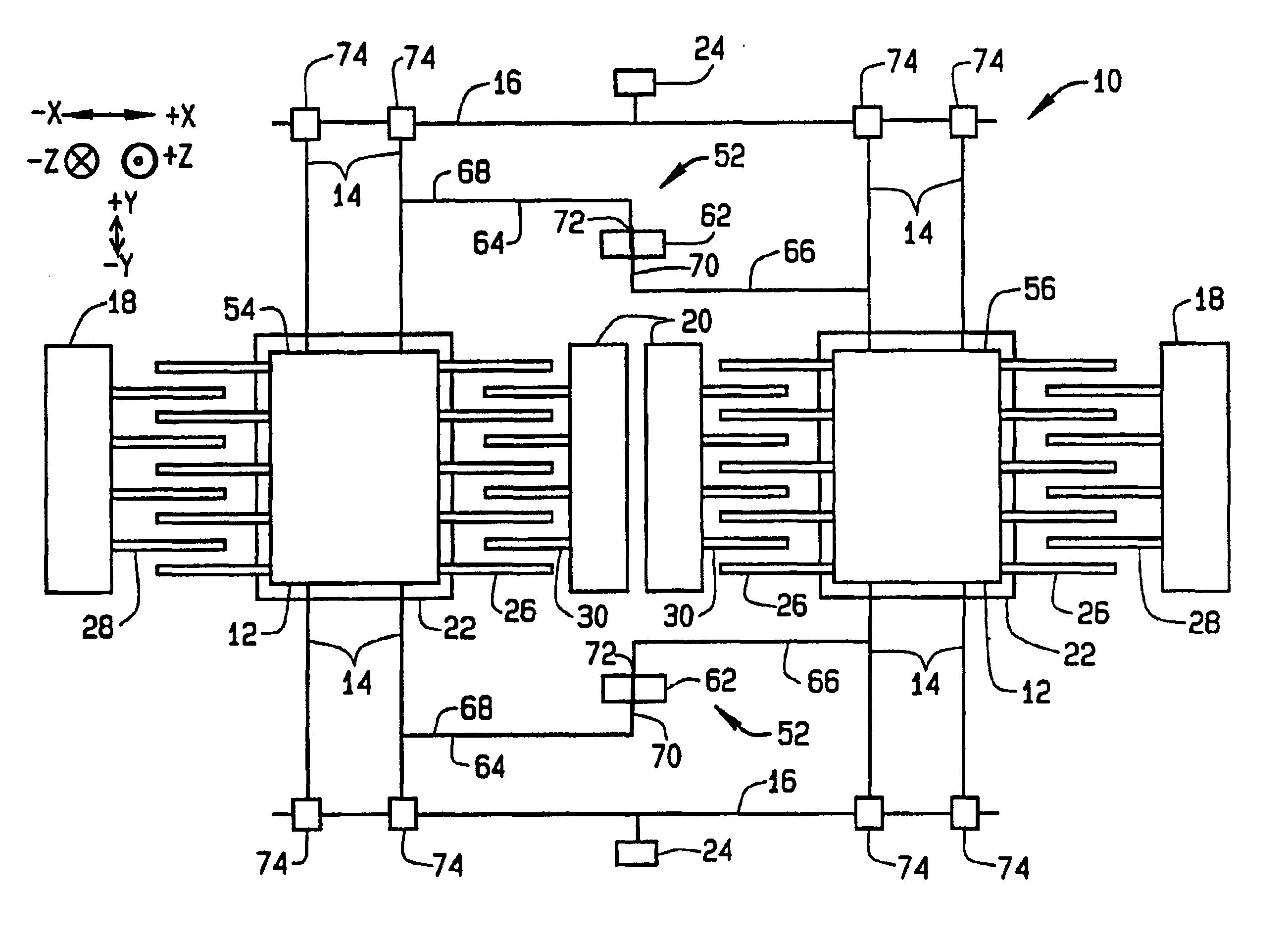
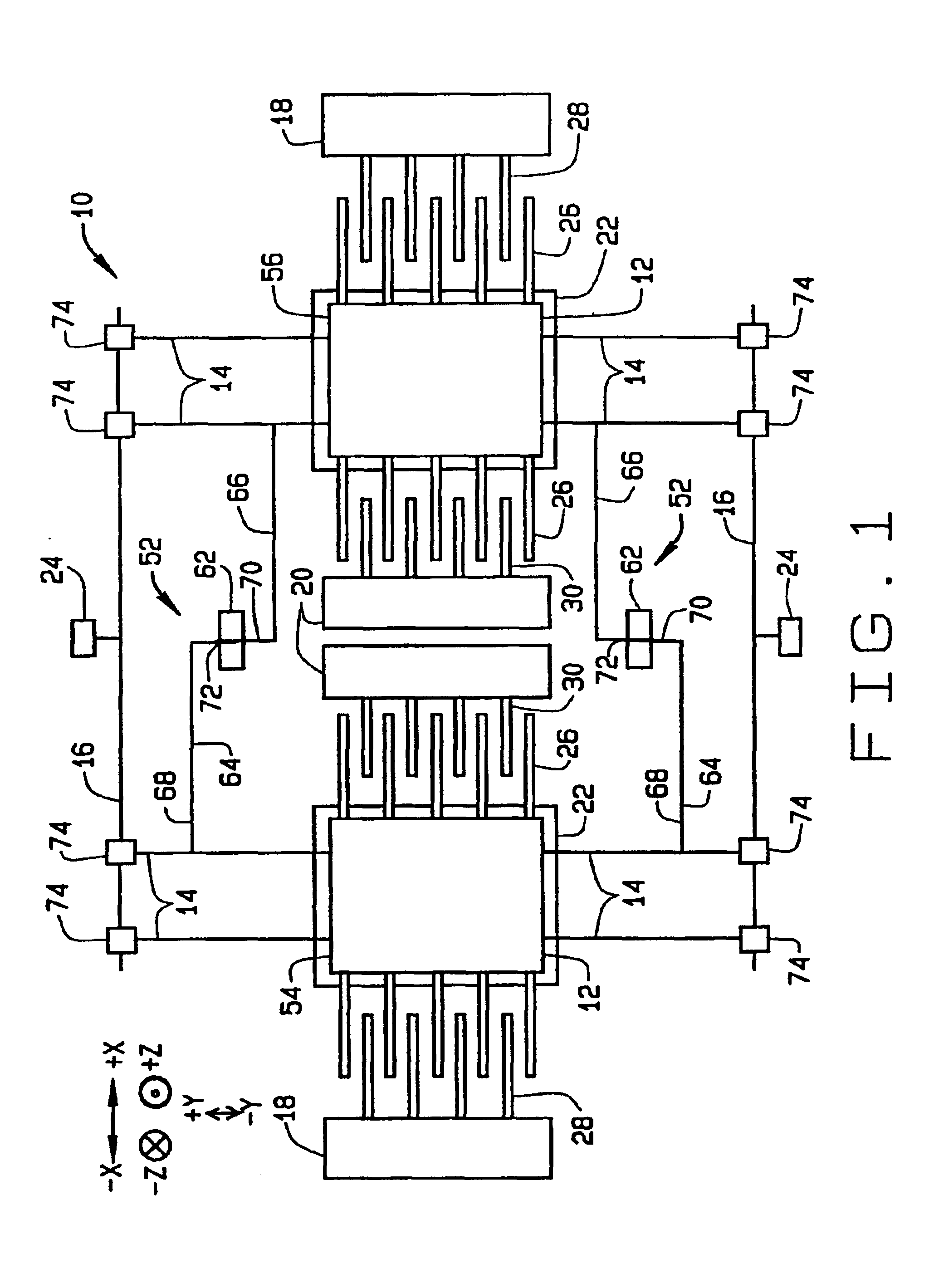
FIG. 1 illustrates a plan view of a micro-electromechanical system (MEMS) gyroscope 10. MEMS gyroscope 10 is formed on a substrate (not shown) and includes at least one proof mass 12, a plurality of suspensions 14 for supporting proof masses 12, and at least one cross beam 16 connected to suspensions 14. In an alternative configuration, suspensions 14 are individually and directly connected to the substrate. MEMS gyroscope 10 also includes motor drive combs 18, motor pickoff combs 20, and sense plates 22, which correspond to individual proof masses 12. Gyroscope 10 also includes anchors 24 mounted on the substrate for support of cross beams 16.

Proof masses 12 are fabricated from any mass suitable for use in a MEMS gyroscope system. In one embodiment, proof mass 12 is a plate of silicon. Other materials compatible with micro-machining techniques may also be utilized. While FIG. 1 shows two proof masses 12, MEMS devices utilizing fewer or greater than two proof masses may also be util...


PUM


Abstract

A method for reducing undesired movements of proof masses in micro-electromechanical systems (MEMS) devices is described where the proof masses are suspended above a substrate by one or more suspensions. The method includes providing an anchor on the substrate substantially between a first proof and suspensions for the first proof mass and a second proof mass and suspensions for the second proof mass, coupling a first portion of a beam to the first proof mass, coupling a second portion of the beam to the second proof mass, and attaching a third portion of the beam to the anchor, the third portion extending between the first portion and second portion of the beam, the anchor and the third portion configured to allow for rotation about an axis perpendicular to the substrate.

Description

BACKGROUND OF THE INVENTIONThis invention relates generally to micro-electromechanical systems (MEMS), and more specifically, to suppression of unwanted frequencies generated during operation of MEMS devices.Micro-electromechanical systems (MEMS) integrate electrical and mechanical components on the same substrate, for example, a silicon substrate, using microfabrication technologies. The electrical components are fabricated using integrated circuit processes, while the mechanical components are fabricated using micromachining processes that are compatible with the integrated circuit processes. This combination makes it possible to fabricate an entire system on a chip using standard manufacturing processes.One common application of MEMS devices is in the design and manufacture of sensor devices. The mechanical portion of the sensor device provides the sensing capability, while the electrical portion of the sensor device processes the information received from the mechanical portion....

Claims


Application Information

Patent Timeline
Patent Type & Authority Patents(United States)
IPC IPC(8): G01C19/56G01C19/5719
CPCG01C19/5719Y10T74/12
Inventor PLATT, WILLIAM P.JOHNSON, BURGESS R.
Owner HONEYWELL INT INC
Why Eureka
Try Eureka