Method for Welding Depending on a Preferred Direction of the Substrate

a technology of substrate welding and preferred direction, which is applied in the direction of machines/engines, manufacturing tools, turbines, etc., can solve the problem of frequently growing grains in an undesirable direction

Inactive Publication Date: 2011-02-10
SIEMENS AG +1
View PDF10 Cites 13 Cited by
  • Summary
  • Abstract
  • Description
  • Claims
  • Application Information

AI Technical Summary

Problems solved by technology

Nevertheless, grains frequent...

Method used


Image

  • Method for Welding Depending on a Preferred Direction of the Substrate
  • Method for Welding Depending on a Preferred Direction of the Substrate
  • Method for Welding Depending on a Preferred Direction of the Substrate

Examples


Embodiment Construction

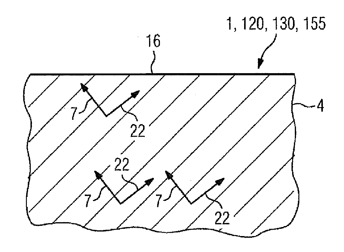
[0015]FIG. 1 is a cross-sectional view of a component 1, 120, 130 (FIGS. 8, 10), 155 (FIG. 9) having a substrate 4 which, in particular in the case of turbine blades or vanes for gas turbines 100 (FIG. 7) or steam turbines, has a superalloy according to FIG. 10.

[0016]The substrate 4 has a directionally solidified structure, i.e. it can consist of columnar grains solidified in columnar form (DS) or of a single crystal (SX). The arrows 7, 22 indicate the preferred crystallographic directions of the substrate 4, i.e. of the single crystal or of the columnar grains (e.g.: [001]=7, [010]=22).

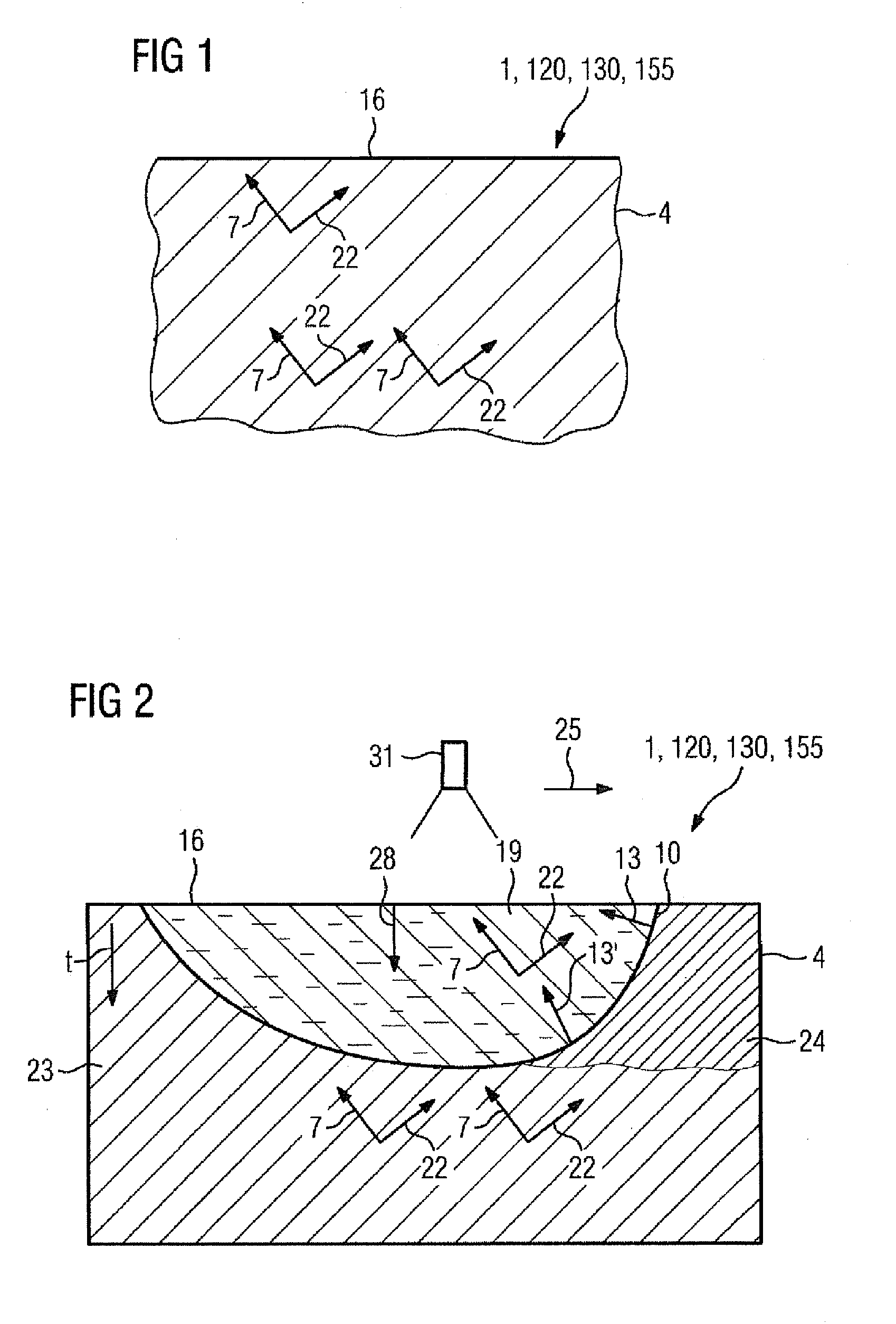
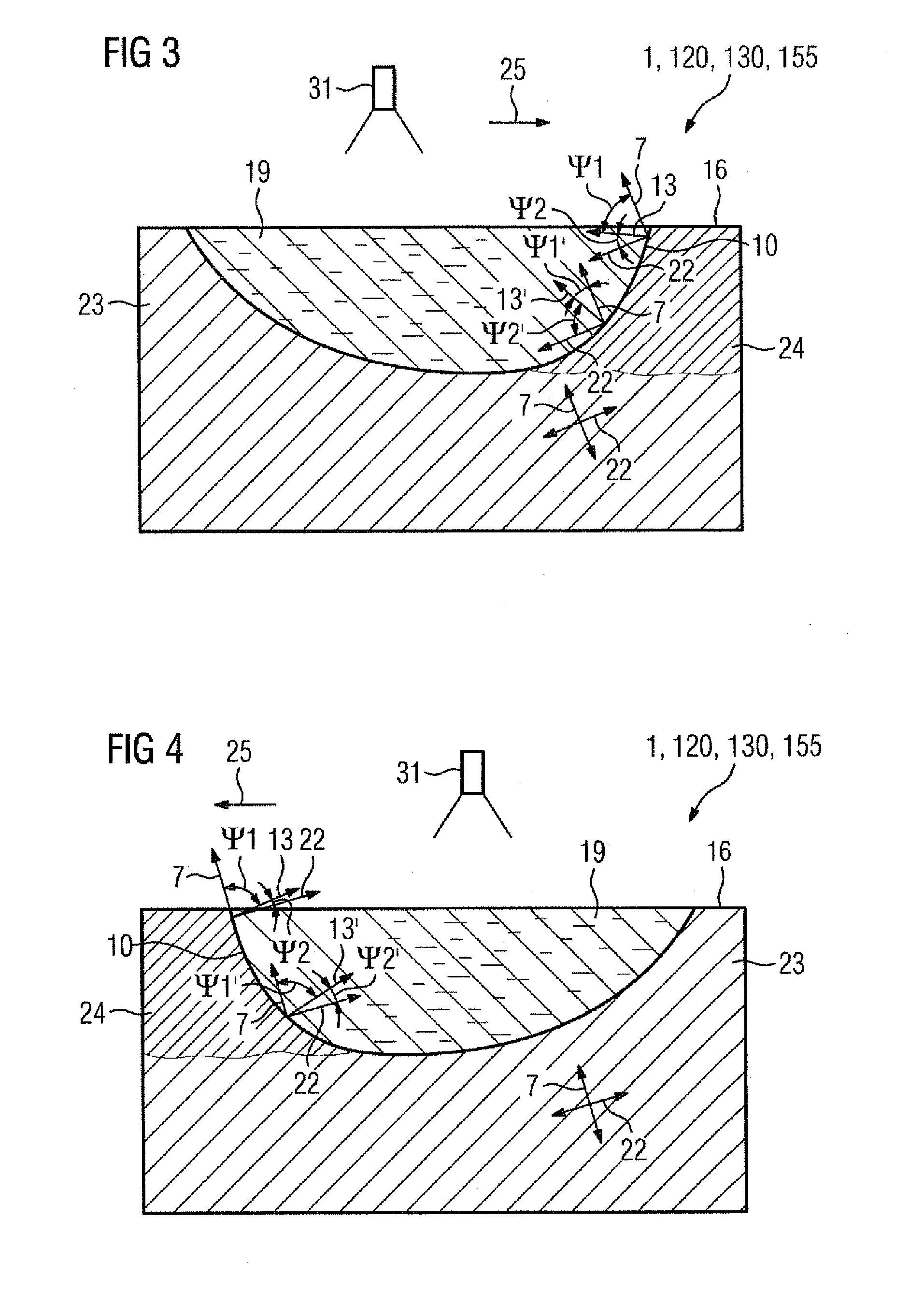
[0017]The substrate 4 has a crack (not shown). The substrate 4 is therefore melted (remelted) in the region of the crack, where the molten region (melt 19, FIGS. 3, 4) should again solidify directionally in a DS or SX structure.

[0018]The substrate 4 may likewise have a point (excessively thin wall, not shown) which is to be strengthened by build-up welding (i.e. the supply of material is required), i...


PUM

PropertyMeasurementUnit
Temperatureaaaaaaaaaa
Structureaaaaaaaaaa
Energyaaaaaaaaaa

Abstract

Welding repairs are often carried out on directionally solidified components that nevertheless do not possess the desired crystallographic surface alignment, which reduces mechanical strength. The method provided selects the direction of travel depending on the crystallographically preferred direction of the substrate such that no more misorientations occur. A laser beam may be used for remelting.

Description

CROSS REFERENCE TO RELATED APPLICATIONS[0001]This application is the US National Stage of International Application No. PCT / EP2009 / 054306, filed Apr. 9, 2009 and claims the benefit thereof. The International Application claims the benefits of German application No. 10 2008 018 708.9 DE filed Apr. 14, 2008. All of the applications are incorporated by reference herein in their entirety.FIELD OF INVENTION[0002]The invention relates to a process for welding a substrate having a preferred direction.BACKGROUND OF INVENTION[0003]Welding is a repair process which is frequently used to close cracks or to apply material. In this case, a laser is often used as the energy source. The laser welding process is also used to repair directionally solidified components, for example turbine blades or vanes of the largest gas turbines, after they have been used, which possibly have cracks as a result of extraordinarily severe loading. These can be components with grains solidified in columnar form (DS)...

Claims


Application Information

Patent Timeline
IPC IPC(8): B23K26/20
CPCB23K26/08B23K2201/001B23K26/3206B23K26/3213B23K26/345C22C19/058B23P6/007F05D2230/232C22C19/055C22C19/056C22C19/057C22C19/07F01D5/28B23K26/32B23K26/342B23K2103/02B23K2103/08B23K2103/26B23K2103/50B23K2101/001
Inventor MOKADEM, SELIMPIRCH, NORBERT
Owner SIEMENS AG
Why Eureka
Try Eureka