Ray-aggregation for ray-tracing during rendering of imagery

a technology of ray-tracing and imagery, applied in the field of computer graphics, can solve the problems of large number of intersection tests, high computation time and memory costs, and often more photorealistic images rendered using global illumination algorithms

Active Publication Date: 2011-02-24
DREAMWORKS ANIMATION LLC
View PDF19 Cites 29 Cited by
  • Summary
  • Abstract
  • Description
  • Claims
  • Application Information

AI Technical Summary

Problems solved by technology

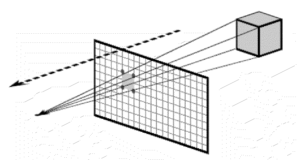
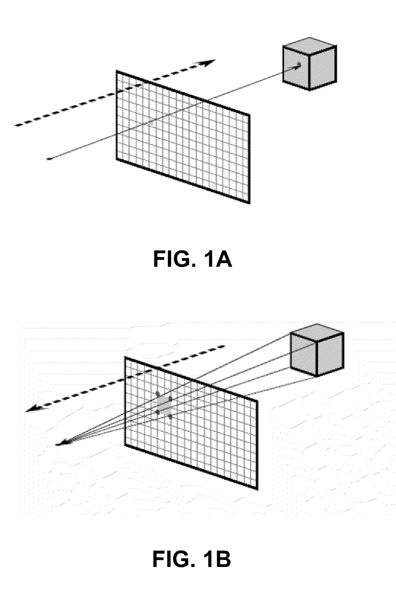
Images rendered using global illumination algorithms often appear more photorealistic but they are more expensive in terms of computation time and memory.
The disadvantage of this naive approach is that it requires a huge number of intersection tests for each ray and can be inefficient and costly.
However, the more the two rays diverge, the greater the possibility that the algorithm will perform many ray-triangle intersection tests unnecessarily.

Method used


Image

  • Ray-aggregation for ray-tracing during rendering of imagery
  • Ray-aggregation for ray-tracing during rendering of imagery
  • Ray-aggregation for ray-tracing during rendering of imagery

Examples


Embodiment Construction

[0027]The following description is presented to enable a person of ordinary skill in the art to make and use the invention, and is provided in the context of particular applications and their requirements. Various modifications to the embodiments will be readily apparent to those skilled in the art, and the generic principles defined herein may be applied to other embodiments and applications without departing from the spirit and scope of the invention. Moreover, in the following description, numerous details are set forth for the purpose of explanation. However, one of ordinary skill in the art will realize that the invention might be practiced without the use of these specific details. In other instances, well-known structures and devices are shown in block diagram form in order not to obscure the description of the invention with unnecessary detail. Thus, the present invention is not intended to be limited to the embodiments shown, but is to be accorded the widest scope consisten...


PUM


Abstract

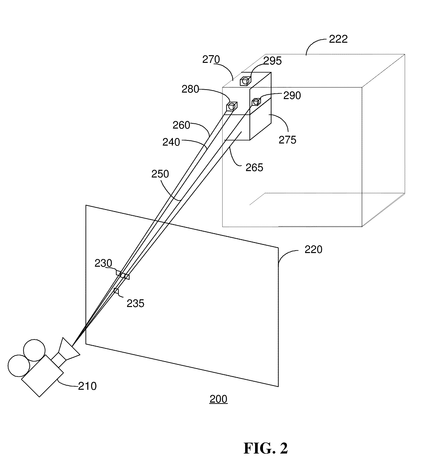
A computer-enabled method for rendering a scene of objects representing physical objects includes projecting a first plurality of rays against a scene and aggregating a second plurality of rays that intersect a bounding volume, wherein the bounding volume encloses an object of the scene, and wherein the second plurality of rays is a portion of the first plurality of rays. The method further includes determining or computing intersections of the second plurality of aggregated rays with the object when the number of the second plurality of aggregated rays exceeds a predetermined value. The method also includes rendering the scene based on the determined intersections of the rays with the object. The second plurality of rays may be aggregated in a bounding volume aggregate data structure for processing.

Description

BACKGROUND[0001]1. Field[0002]This invention relates generally to computer graphics, and more specifically to computer systems and processes for rendering data to produce images.[0003]2. Related Art[0004]In computer graphics, rendering generally includes the process of generating a two-dimensional (2D) image using a model that describes three-dimensional (3D) objects within a scene. Many methods generating images of three-dimensional scene information have been developed. Primary among these are ray-tracing and scanline rendering, and an image renderer may employ a number of rendering methods, including aspects of both of these, to obtain a final image. Both ray-tracing and scanline rendering develop an image made up of rectangular samples called pixels, but each algorithm implements it in a different way, and each algorithm has virtues and drawbacks.[0005]As shown in FIG. 1A, the ray-tracing approach generates an image by tracing the path of rays from a virtual camera through pixel...

Claims


Application Information

Patent Timeline
Patent Type & Authority Applications(United States)
IPC IPC(8): G06T15/00
CPCG06T15/06
Inventor SMYTH, EVAN P.
Owner DREAMWORKS ANIMATION LLC
Why Eureka
Try Eureka