
Display devices having micro-reflectors and color filters

a technology of color filter and display device, which is applied in the direction of static indicating device, optics, instruments, etc., can solve the problem of most of it being lost to the viewer, and achieve the effect of enhancing the brightness of the display panel, particularly the electrophoretic display panel, and enhancing the structur

Active Publication Date: 2011-02-24
E INK CORPORATION
View PDF55 Cites 17 Cited by
  • Summary
  • Abstract
  • Description
  • Claims
  • Application Information

AI Technical Summary

Benefits of technology

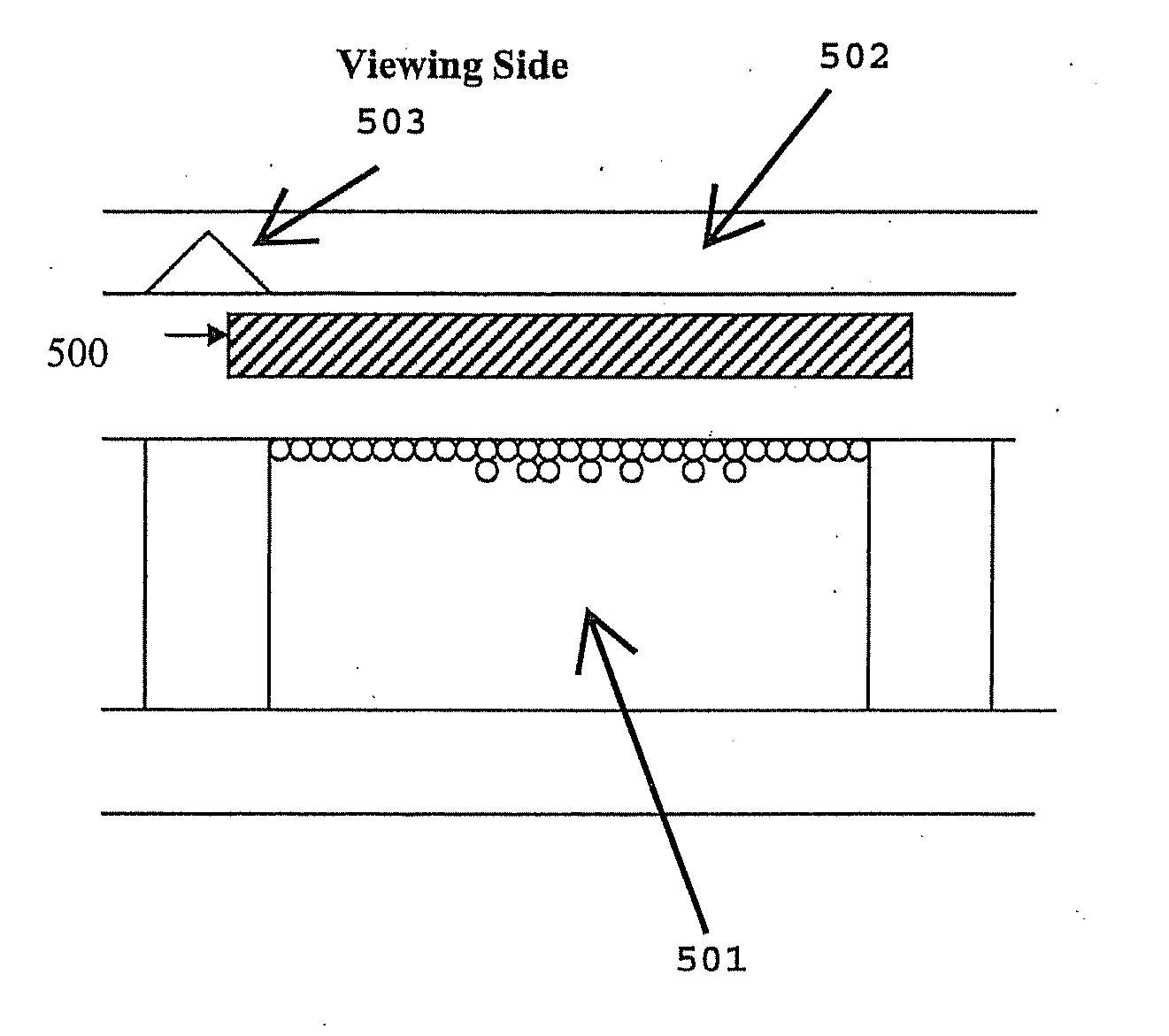
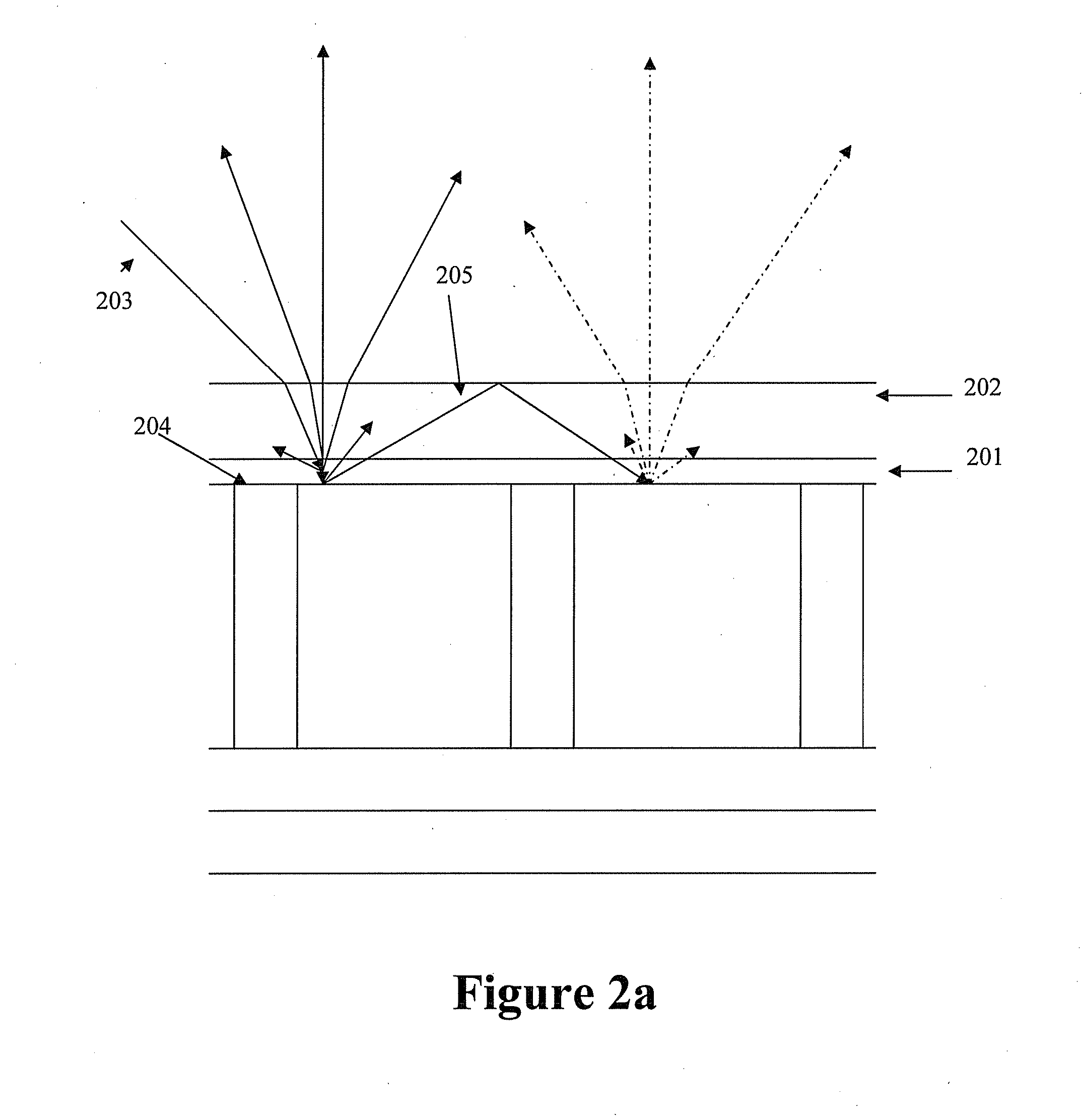
[0003]The brightness of a display panel, particularly an electrophoretic display panel, may be enhanced through the use of a brightness enhancement structure comprising micro-reflectors fabricated on top of the viewing surface of the display panel. This may be accomplished by building a structure on top of the display cells to deflect the light striking the top viewing surface. Such a structure can serve two purposes. First, it can divert the illumination light from reaching the wall of the display cells onto the reflective surface of the display panel, thus saving this light which would have otherwise been transmitted by, or absorbed into, display cell walls (i.e., an inactive part of the display panel). Secondly, without the structure on top of the display cells, light scattered by the display panel in reflection which strikes the surface of the transparent material on top of the display panel at an angle greater than the critical angle is reflected back onto the display panel and most of it is lost to the viewer. The micro-reflector structure intercepts these rays and redirects them more towards the viewer because they strike the top surface at an angle less than the critical angle and are thus transmitted through the surface, achieving a second source of brightness enhancement. It is believed that such brightness enhancement techniques can potentially achieve a brightness enhancement of as much as two times of the original brightness.

Problems solved by technology

Secondly, without the structure on top of the display cells, light scattered by the display panel in reflection which strikes the surface of the transparent material on top of the display panel at an angle greater than the critical angle is reflected back onto the display panel and most of it is lost to the viewer.

Method used


Image

  • Display devices having micro-reflectors and color filters
  • Display devices having micro-reflectors and color filters
  • Display devices having micro-reflectors and color filters

Examples


Embodiment Construction

[0026]A “display device,” as used herein, refers to a device that displays images. The display devices in this application include all types of reflective display devices such as electrophoretic display devices and liquid crystal display devices. Electrophoretic display devices are preferred for this invention.

[0027]“Micro-structures” as used herein, refer to cavities. “Micro-reflectrors” as used herein, refer to micro-structures having a metal layer coated on its surface. Micro-structures or Micro-reflectors are illustrated in FIGS. 2b (303), 3a-3c (303), 3k-3m (303), FIG. 4 (403), FIG. 7 (703), and FIG. 8a (803). The dimensions of the micro-reflectors are illustrated in the present application. The cavities (i.e., micro-reflectors) in general may have a width and height between 1-1000 microns, preferably 10-500 microns, and more preferably 20-300 microns.

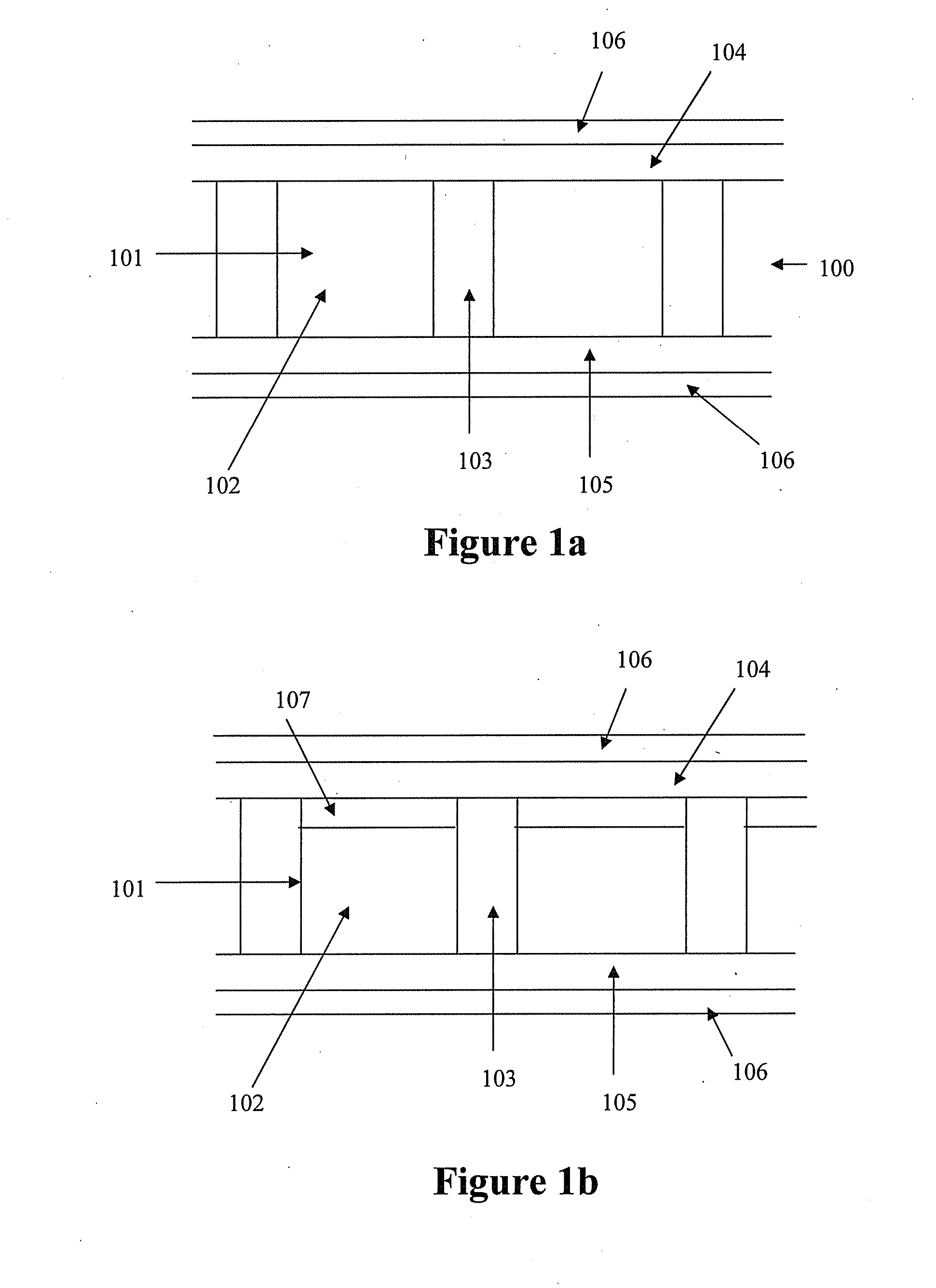
[0028]FIG. 1a illustrates a display device (100). The device comprises an array of display cells (101) filled with a display flu...


PUM

PropertyMeasurementUnit
heightaaaaaaaaaa
heightaaaaaaaaaa
heightaaaaaaaaaa

Abstract

The present invention relates to a process for manufacturing a brightness enhancement structure comprising micro-reflectors. The process comprises forming an array of micro-structures by embossing; and depositing a metal layer over the surface of the micro-structures. The present invention also relates to a process for manufacturing a display device comprising micro-reflectors. The present invention further relates to a display device comprising micro-reflectors and color filters.

Description

[0001]This application is a continuation of U.S. application Ser. No. 12 / 323,300, filed Nov. 25, 2008, now U.S. Pat. No. 7,830,592; which claims priority to U.S. Provisional Application Nos. 60 / 991,600, filed Nov. 30, 2007; and 61 / 030,140, filed Feb. 20, 2008. The above applications are incorporated herein by reference in their entirety.FIELD OF THE INVENTION[0002]The present application describes a brightness enhancement structure comprising micro-reflectors and display devices having such a brightness enhancement structure on its viewing side. The present invention is directed to manufacturing processes for the brightness enhancement structure and display devices having the brightness enhancement structure.SUMMARY OF THE INVENTION[0003]The brightness of a display panel, particularly an electrophoretic display panel, may be enhanced through the use of a brightness enhancement structure comprising micro-reflectors fabricated on top of the viewing surface of the display panel. This m...

Claims


Application Information

Patent Timeline
Patent Type & Authority Applications(United States)
IPC IPC(8): G02B26/00
CPCG02B5/0242G02B5/0278G02F2001/133507G02F1/133553G02F1/167G02F1/133504G02F1/1677G02F1/133507
Inventor SPRAGUE, ROBERT A.CHAUG, YI-SHUNGZANG, HONGMEIWANG, XIAOJIAKANG, GARY
Owner E INK CORPORATION
Learn More