White film for surface light source reflecting members

a technology of surface light source and white film, which is applied in the direction of instruments, synthetic resin layered products, mechanical instruments, etc., can solve the problems that the edge light system cannot increase the brightness of recent wide screen liquid crystal tvs, and its reflectivity is lowered, so as to reduce light loss, improve the effect of brightness and improved results

Inactive Publication Date: 2007-01-18
TORAY IND INC
View PDF6 Cites 6 Cited by
  • Summary
  • Abstract
  • Description
  • Claims
  • Application Information

AI Technical Summary

Benefits of technology

[0012] One preferred embodiment of the invention is described below, in which polyester is used as the white film base material. To whiten the polyester film, for example, employable are a method of adding thereto various types of white dye or pigment; and a method of forming fine voids inside it as in the above. For attaining better results in the invention, preferred is the method of forming fine voids inside the film. For forming such fine voids inside it, for example, employable are (1) a method of adding a foaming agent to the resin to thereby make the resin film foamed by heat in the step of extrusion or film processing or foamed through chemical decomposition; (2) a method of adding a vapor such as carbon dioxide or a vaporizable substance to the resin during or after its extrusion to thereby make the resin film foamed; (3) a method of adding a thermoplastic resin not miscible with polyester to the resin, melt-extruding the resin mixture, and monoaxially or biaxially stretching the resin film; and (4) a method of adding organic or inorganic fine particles to the resin, melt-extruding the mixture, and monoaxially or biaxially stretching the resin film. In the invention, the fine voids formed in the film are to increase the reflective interface therein, for which, therefore, preferred is the method (3) or (4).
[0013] The size of the voids formed in the methods as above (this is the size of the cross section of the voids cut in the direction of the thickness of the film) preferably falls between 0.5 μm2 and 50 μm2, more preferably between 1 μm2 and 30 μm2, in view of the increased brightness of the film. The cross-sectional profile of the voids may be circular or oval. Preferably, the film is so constituted that at least one void exists everywhere in its vertical direction running from the top face to the back face thereof. When the film is formed into a reflecting sheet, the light from a light source enters it through the film surface, and it is the best that all the incident light having reached the reflecting sheet is entirely reflected by the voids inside the film. In fact, some light will pass through the film, and it shall be a light loss. To compensate it, the surface of the film opposite to the surface thereof that receives light (facing the light source) is preferably coated with metal such as aluminium or silver through vapor deposition. In addition, for reducing the light loss through the fine voids-containing polyester film, it is also desirable that the surface of the film is coated with a layer that contains fine voids formed by organic or inorganic fine particles. The surface layer may be formed by co-extruding a polyester resin that contains organic or inorganic fine particles, along with the resin for the fine voids-containing film, followed by stretching the resulting composite film at least in one direction. Preferably, the voids in the surface layer are smaller than those in the inner layer of the composite film for increasing the brightness of the film. The ratio (void size in surface layer / void size in inner layer) is not specifically defined, but preferably falls between 0.05 and 0.8, more preferably between 0.07 and 0.7, most preferably between 0.1 and 0.6. The void size can be controlled by controlling the size of the particles to be added to film-forming resins.
[0014] Now described hereinunder are the resin not miscible with polyester resin, and the organic or inorganic particles to be added to the surface layer and the inner layer, which are to form voids in polyester films. The resin not miscible with polyester film (hereinafter referred to as immiscible resin) is a thermoplastic resin except polyester, and this can disperse in polyester, forming particles therein. Preferred examples of the resin of the type are polyolefin resins such as polyethylene, polypropylene, polybutene, polymethylpentene; as well as polystyrene resins, polyacrylate resins, polycarbonate resins, polyacrylonitrile resins, polyphenylene sulfide resins, and fluororesins. These may be homopolymers or copolymers, and two or more different types of these may be combined for use herein. Especially preferred are resins that yield a great critical surface tension difference from polyester and hardly deform in heat treatment after stretching. For these, preferred are polyolefin resins, and more preferred is polymethylpentene. The content of the immiscible resin to be in the white film is not specifically defined, and may be suitably determined so that the film is not broken while formed and the brightness of the film can be increased by the voids formed from the nuclei of the immiscible resin in the film. In general, it falls preferably between 3 and 35% by weight, more preferably between 4 and 30% by weight, most preferably between 5 and 25% by weight. If the content is smaller than 3% by weight, the brightness of the film could not increase so much; but if larger than 35% by weight, the film may be broken while formed.
[0015] The inorganic fine particles to be added to the inner layer and / or the surface layer are preferably those that may be nuclei by themselves to form voids in the layers. For these, for example, usable are calcium carbonate, magnesium carbonate, zinc carbonate, titanium oxide (anatase type, rutile type), zinc oxide, barium sulfate, zinc sulfide, basic zinc carbonate, titanium mica, antimony oxide, magnesium oxide, calcium phosphate, silica, alumina, mica, talc, kaolin. Of those, especially preferred are calcium carbonate and barium carbonate that absorb little visible light falling within a range of from 400 to 700 nm. Particles that absorb visible light are problematic as the brightness of the film containing them is lowered. The organic fine particles are preferably those not fusing in melt extrusion. For these, especially preferred are crosslinked particles of crosslinked styrene or crosslinked acryl. The organic fine particles may be hollow. One or more different types of these fine particles may be used herein either singly or as combined. The particle size is not specifically defined, generally falling between 0.05 and 15 μm, preferably between 0.1 and 10 μm, more preferably between 0.3 and 5 μm. If their size is smaller than 0.05 μm, the particles could not yield good voids in films; but, on the contrary, if larger than 15 μm, it is unfavorable since the film surface may be too much roughened. In case where fine particles are in the surface layer and immiscible resin is in the inner layer, it is desirable that the size of the voids formed from the nuclei of the fine particles in the surface layer is smaller than that of the size of the voids formed in the inner layer in order that the brightness of the film is higher. Also preferably, the content of the fine particles in the white film falls between 1 and 30% by weight, more preferably between 2 and 25% by weight, most preferably between 3 and 20% by weight. If the content is smaller than 1% by weight, the brightness of the film could not be increased to a desired degree; but, on the contrary, if larger than 30% by weight, the film may be broken while formed.
[0016] The specific gravity of the voids-containing white film, which is a criterion of the void content of the film, is preferably not smaller than 0.1 but smaller than 1.3. If the specific gravity of the film is smaller than 0.1, it is problematic in that the mechanical strength of the film is low and the film is readily folded and is difficult to handle. On the other hand, if the specific gravity of the film is larger than 1.3, the void content thereof is too low, and therefore the reflectivity of the film is low and the brightness thereof may be insufficient. In case where the film-forming thermoplastic resin is polyester, the lowermost limit of the specific gravity of the film is preferably 0.4. If its specific gravity is smaller than 0.4, the void content of the film is too high, and it is problematic in that the film is frequently broken while formed.
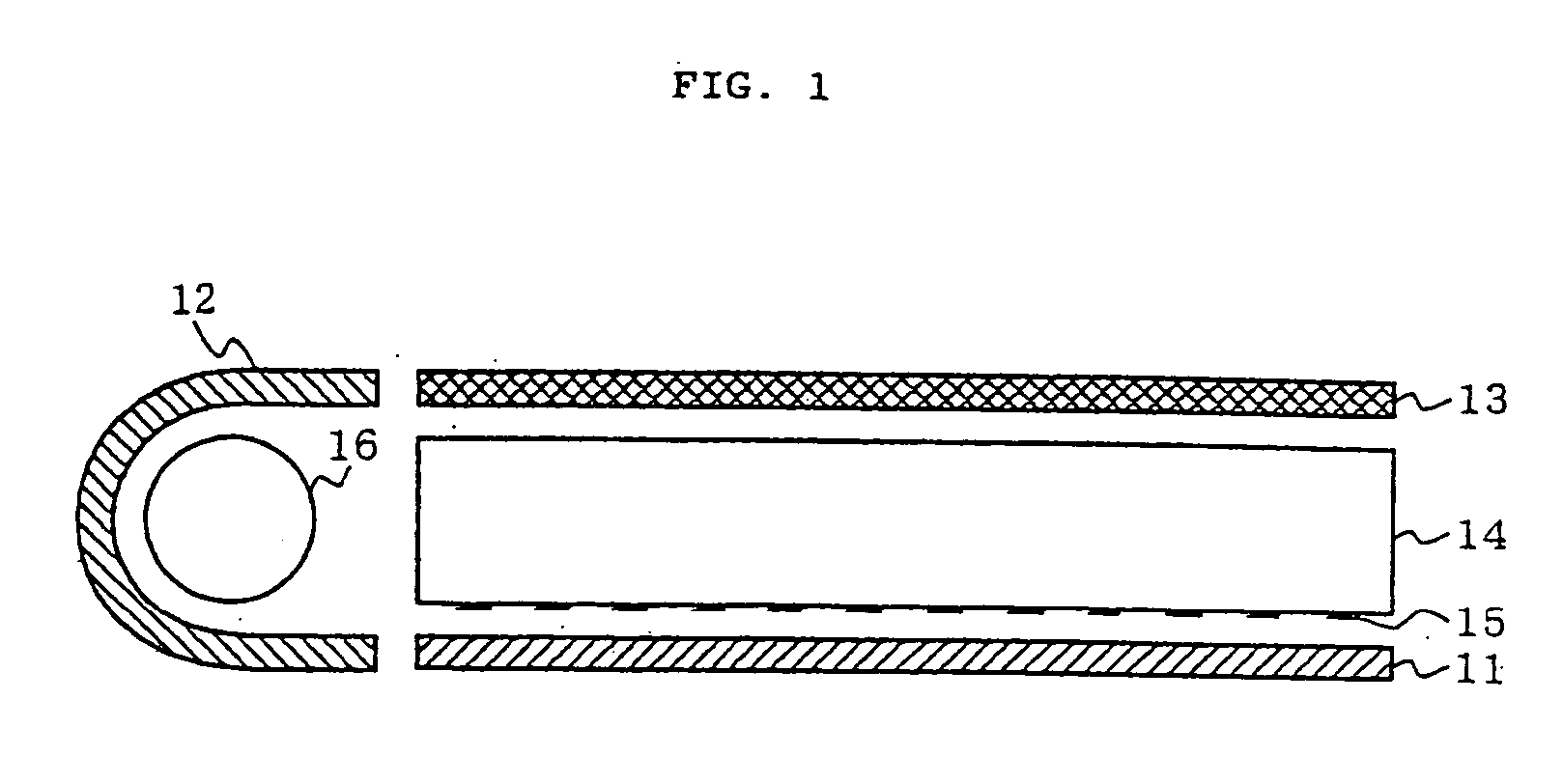
[0017] The reflecting structure for surface light source is a tabular structure that is combined with a surface light source for light reflection thereon, as so mentioned hereinabove. Concretely, it includes reflecting sheets for edge lights-type surface light sources for liquid crystal display screens, reflecting sheets for direct back light-type surface light sources, and reflectors around cold cathode-ray tubes. For the reflecting structure for surface light source of the type, the degree of whiteness of the reflecting sheet is preferably higher for bettering the color tone of screens, and bluish reflecting sheets are preferred to yellowing ones. Taking this into consideration, it is desirable to add a fluorescent brightener to the white film. The fluorescent brightener may be any commercially-available one, including, for example, Uvitex (by Ciba-Geigy), OB-1 (by Eastman), TBO (by Sumitomo Seika), Keikol -(by Nippon Soda), Kayalite (by Nippon Kayaku), and Leucopoor EGM (by Clariant Japan). Preferably, the content of the fluorescent brightener in the white film falls between 0.005 and 1% by weight, more preferably between 0.007 and 0.7% by weight, most preferably between 0.01 and 0.5% by weight. If its content is smaller than 0.005% by weight, the fluorescent brightener may be ineffective; but if larger than 1% by weight, it is unfavorable since too much fluorescent brightener rather yellows the white film. In case where the white film is a composite film, the fluorescent brightener is more preferably added to the surface layer of the film.

Problems solved by technology

However, the edge light system could not increase the brightness of recent wide screens of liquid crystal TVs, for which, therefore, a direct back light system is being employed.
However, reflectors and reflecting sheets of conventional .film are problematic in that the film is aged and yellowed when used for a long time and therefore its reflectivity is lowered with time and the screen brightness is after all lowered.

Method used


Image

  • White film for surface light source reflecting members

Examples


example 1

[0052] Raw material mixtures mentioned below were fed into a composite film-forming device equipped with an extruder A and an extruder B.

Extruder A:

[0053] 90 parts by weight of PET chips dried in vacuum at 180° C. for 4 hours, 10 parts by weight of polymethylpentene, and 1 part by weight of polyethylene glycol having a molecular weight of 4000.

Extruder B:

[0054] 100 parts by weight of PET chips containing 15% by weight of barium sulfate particles having a mean particle size of 1 μm, and dried in vacuum at 180° C. for 4 hours, and 3 parts by weight of PET master chips containing 1% by weight of a fluorescent brightener, OB-1 (by Eastman), and dried in vacuum at 180° C. for 4 hours.

[0055] In the extruders A and B, the mixtures were separately melted and extruded out of them at 290° C. in such a manner that the melt from the extruder A could be an inner layer sandwiched between two outer layers of the melt from the extruder B, and the resulting laminate melt was extruded out thro...

examples 2 to 5

[0058] A white film was prepared in the same manner as in Example 1. The polyurethane-coated surface of the white film was coated with the same light stabilizer-containing coating liquid as in Example 1 to form thereon a coating layer having a dry thickness of 1 μm (Example 2), 3 μm (Example 3), 7 μm (Example 4), or 10 μm (Example 5). These samples were all superior to the sample of Comparative Example 1, though the durability of the samples of which the thickness of the coating layer was smaller than that of the sample of Example 1 (Examples 2 and 3) lowered in some degree and the initial brightness of the samples of which the thickness of the coating layer was larger than that of the sample of Example 1 (Examples 4 and 5) lowered in some degree.

example 6

[0059] A white film was prepared in the same manner as in Example 1. The polyurethane-coated surface of the white film was coated with a coating liquid having the composition mentioned below to form thereon a light stabilizer-containing coating layer, in the same manner as in Example 1. The thus-fabricated white film for a reflecting structure for surface light sources was yellowed little in the durability test, and its mean reflectance reduction and brightness reduction were small, as in Table 1.

[0060] (Coating Liquid for Forming Coating Layer)

U-Double UV714 (40% solution by Nippon Shokubai)10.0 gSumidule N3200 (curing agent, by Sumitomo-Bayer Urethane) 0.5 gEthyl acetate / toluene (1 / 1 by weight)12.0 g[Examples 7, 8, 9]

[0061] A white film was prepared in the same manner as in Example 6. The polyurethane-coated surface of the white film was coated with a coating liquid that had been prepared by mixing 20.0 g of the coating liquid in Example 1 with 0.13 g (solid content, 3% by weig...


PUM

PropertyMeasurementUnit
reflectanceaaaaaaaaaa
particle sizeaaaaaaaaaa

Abstract

A white film for a reflecting structure for surface light sources, which contains voids inside it and has a light stabilizer-containing coating film formed on at least one surface of it, is aged little with time and its brightness lowers little even when used for a long time. The white film ensures good image quality of display screens for a long time, and it is favorable to reflecting sheets and reflectors in edge light-type and direct back light-type surface light sources for liquid crystal display screens.

Description

TECHNICAL FIELD [0001] The present invention relates to improvements on white film for a reflecting structure for surface light source. More precisely, the invention relates to a structure of white film which is used in reflecting sheets and reflectors for edge light-type and direct back light-type, surface light sources for liquid crystal display screens, and of which the brightness lowers little when used for a long time. BACKGROUND ART [0002] For lighting units for liquid crystal display screens, widely used is a edge light system in which a cold cathode-ray tube serving as the source of light is disposed at the edge of a light guide plate (JP-A 62104 / 1988). In the lighting system of the type, a reflector is disposed around the cold cathode-ray tube for increasing the lighting efficiency therein, and a reflecting sheet is disposed below the light guide plate for efficiently reflecting the light having been diffused through the light guide plate toward a liquid crystal display scr...

Claims


Application Information

Patent Timeline
Patent Type & Authority Applications(United States)
IPC IPC(8): B32B27/00F21V8/00G02B6/00
CPCG02B6/0043G02B6/0055G02B6/0065Y10T428/24033Y10T428/25Y10T428/263Y10T428/261Y10T428/249953Y10T428/249981Y10T428/249986Y10T428/249991Y10T428/249992Y10T428/31786B29C48/0018C08J5/18C08J2367/00C08K5/005C08L2666/54C09D7/40
Inventor MIMURA, TAKASHITANAKA, YOSHIOOOWATARI, HISASHI
Owner TORAY IND INC
Why Eureka
Try Eureka