Eureka AIR delivers breakthrough ideas for toughest innovation challenges, trusted by R&D personnel around the world.

Electrical connector with a stable structure

Active Publication Date: 2011-02-24
HON HAI PRECISION IND CO LTD
View PDF6 Cites 5 Cited by
  • Summary
  • Abstract
  • Description
  • Claims
  • Application Information

AI Technical Summary

Benefits of technology

[0008]According to another aspect of the present invention, a method of making an electrical connector, comprises: a first housing having a mating surface and a mounting surface at two sides thereof; and a second housing retained to the first housing and having a joint surface to joint with the mounting surface; wherein the first housing defines a locking slot and a position slot respectively recessed from the mounting surface, and the second housing is formed with a spring arm locking with the locking slot to prevent the second housing from departing from the first housing along an assembling direction of the second housing, and a position projection engaging with the position slot to prevent the second housing from moving along a deformed direction of the spring arm.

Problems solved by technology

If the blocks are made too big, the blocks can not be easily assembled to the position slots; while if the blocks are made too small, the blocks can not be stably positioned in the position slots, and easily depart from the position slots, then the spacer can not stably position the contacts.

Method used


Image

  • Electrical connector with a stable structure
  • Electrical connector with a stable structure
  • Electrical connector with a stable structure

Examples


Embodiment Construction

[0017]In the following description, numerous specific details are set forth to provide a thorough understanding of the present invention. However, it will be obvious to those skilled in the art that the present invention may be practiced without such specific details. In other instances, well-known circuits have been shown in block diagram form in order not to obscure the present invention in unnecessary detail. For the most part, details concerning timing considerations and the like have been omitted inasmuch as such details are not necessary to obtain a complete understanding of the present invention and are within the skills of persons of ordinary skill in the relevant art.

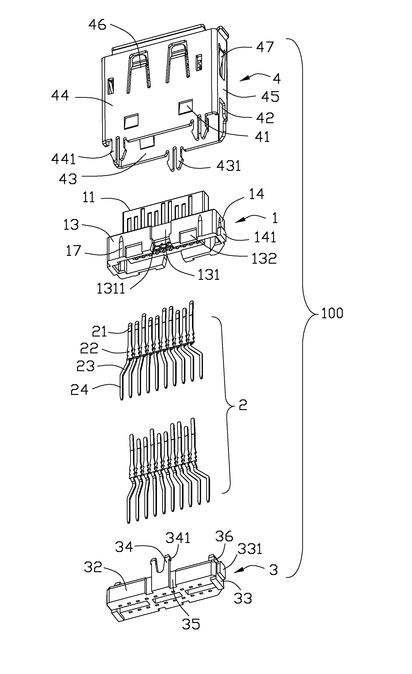
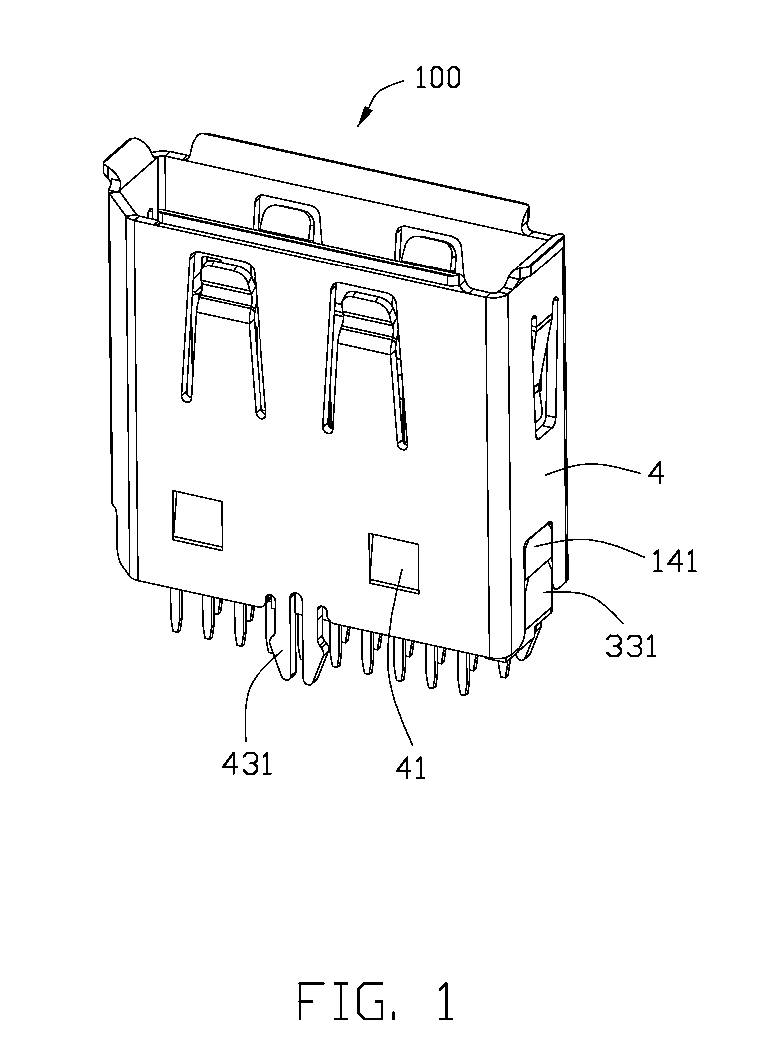
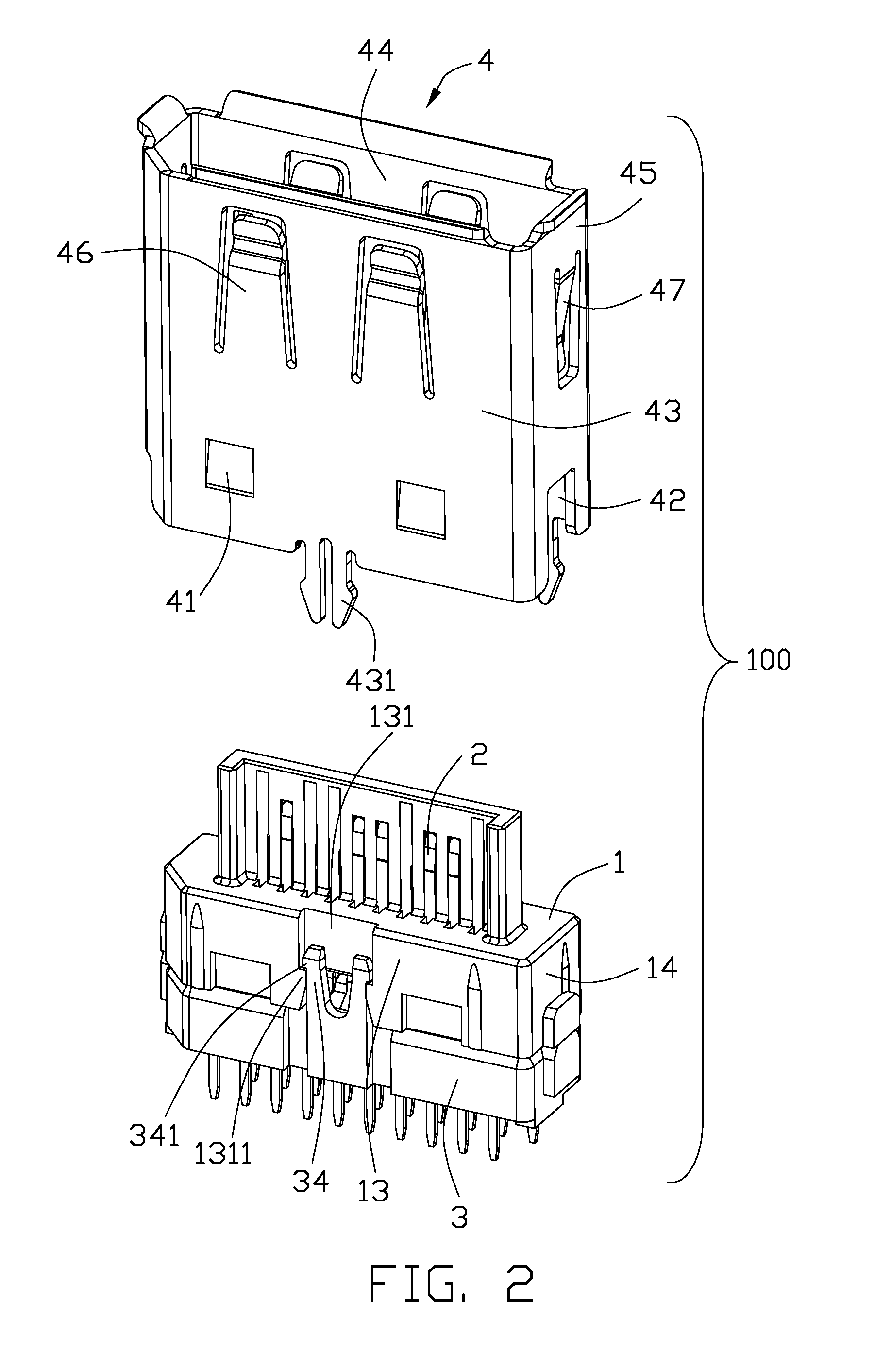
[0018]Reference will be made to the drawing figures to describe the present invention in detail, wherein depicted elements are not necessarily shown to scale and wherein like or similar elements are designated by same or similar reference numeral through the several views and same or similar terminology.

[0019]R...


PUM


Abstract

An electrical connector (100) includes a first housing (1) and a second housing (3) retained to the first housing (1). The first housing (1) has a mating surface (11) and a mounting surface (12) at two sides thereof. The second housing (3) has a joint surface (31) to joint with the mounting surface (12). The first housing (1) defines a locking slot (131) recessed from the mounting surface (12). The second housing (3) is formed with a pair of spring arms (34) extending out of the joint surface (31) to resist opposed two inner walls of the locking slot (131).

Description

BACKGROUND OF THE INVENTION[0001]1. Field of the Invention[0002]The present invention relates to electrical connectors, more particularly to an electrical connector with a stable structure.[0003]2. Description of Related Art[0004]Electrical connectors are widely used in electronic device. An electrical connector usually includes an insulative housing, a number of contacts retained in the insulative housing and a spacer retained on the insulative housing for positioning the contacts. The insulative housing has a pair of side walls and a cavity between the side walls for receiving the spacer. Each side wall defines a position slot extending along a front to back direction at an inner side thereof. The position slots communicate with the cavity. The spacer defines a plurality of through holes for receiving a tail portion of the contacts. Besides, the spacer is formed with a pair of blocks at two sides thereof to lock with the position slots of the side walls for positioning the spacer ...

Claims


Application Information

Patent Timeline
IPC IPC(8): H01R13/502
CPCH01R13/65802H01R13/506H01R13/6582
Inventor XIONG, FENGZHU, ZI-QIANGHU, LUN-SONGHAN, HONG-QIANG
Owner HON HAI PRECISION IND CO LTD
Why Eureka
Eureka Blog
Learn More