A method and system for determining the relation between a robot coordinate system and a local coordinate system located in the working range of the robot

a robot and local coordinate technology, applied in the direction of electric programme control, program control, instruments, etc., can solve the problem of less easy to understand for the programmer, and achieve the effect of simple, quick and accura

Inactive Publication Date: 2011-02-24
ABB (SCHWEIZ) AG
View PDF15 Cites 54 Cited by
  • Summary
  • Abstract
  • Description
  • Claims
  • Application Information

AI Technical Summary

Benefits of technology

[0004]The object of the present invention is to provide a method for determining the relation between a local coordinate system located in the working range of the robot and the robot coordinate system, which method is simple, quick and accurate.

Problems solved by technology

A basic problem in robot installations and commissioning of robot cells is the identification of the relation of the robot to a work piece to be processed by the robot.
The same problem arises in cases when the robot holds the work piece to be processed and a tool is located in the working range of the robot.
However, this will be less easy to understand for the programmer.

Method used


Image

  • A method and system for determining the relation between a robot coordinate system and a local coordinate system located in the working range of the robot
  • A method and system for determining the relation between a robot coordinate system and a local coordinate system located in the working range of the robot
  • A method and system for determining the relation between a robot coordinate system and a local coordinate system located in the working range of the robot

Examples


Embodiment Construction

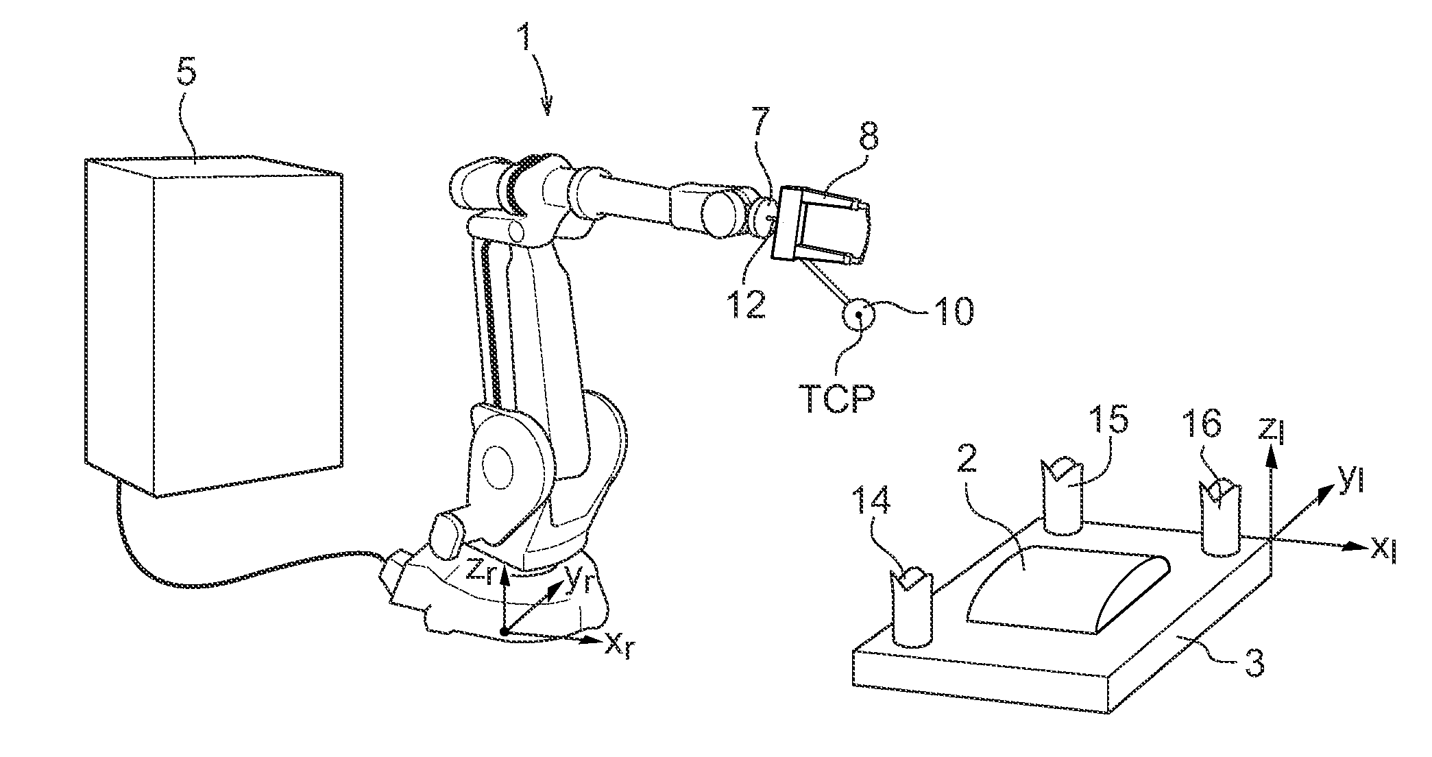
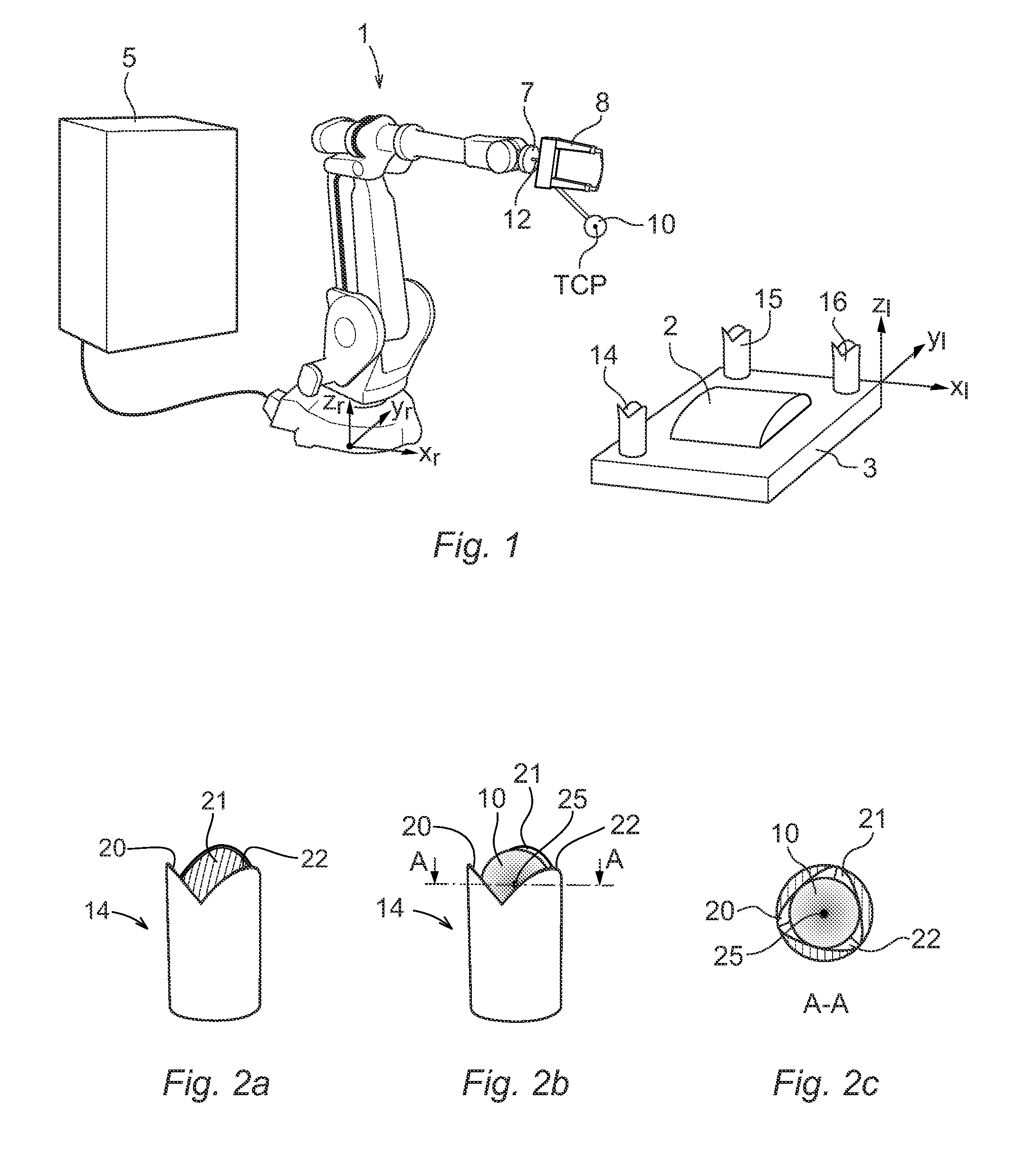
[0033]FIG. 1 shows a system for determining the relation between a local coordinate system xl, yl, zl, and a robot coordinate system xr, yr, zr according to an embodiment of the invention. In this example, the robot coordinate system is located in the base of the robot and is denoted the base coordinate system of the robot. In this example, the local coordinate system is a work piece coordinate system and is related to a work piece 2 to be processed by the robot and which is fixedly hold by a fixture 3.

[0034]The robot 1 is provided with a robot controller 5 including at least one processor, memory and communication means. In this example, the robot controller 5 is utilized for carrying out most of the steps in the method according to the invention. The robot 1 comprises a tool flange 7 for attaching a tool 8. A first calibration object 10 in the form of a male calibration object including a sphere 10 is fixedly attached to the tool 8, and accordingly fixedly attached to the robot, d...


PUM


Abstract

The present invention relates to a method and a system for determining the relation between a local coordinate system located in the working range of an industrial robot (1) and a robot coordinate system. The method comprises: attaching a first calibration object (10) in a fixed relation to the robot, determining the position of the first calibration object in relation to the robot, locating at least three second calibration objects (14, 15, 16) in the working range of the robot, wherein at least one of the calibration objects is a male calibration object having a protruding part shaped as a sphere, and at least one of the calibration objects is a female calibration object comprising at least two nonparallel, inclining surfaces arranged to receive the sphere so that the sphere is in contact with the surfaces in at least one reference position, determining a reference position for each of the second calibration objects in the local coordinate system, for each second calibration object moving the robot until the sphere is in mechanical contact with the surfaces of the calibration object, reading the position of the robot when the sphere is in mechanical contact with all of the surfaces, and calculating the relation between the local coordinate system and the robot coordinate system based on the position of the first calibration object in relation to the robot, the reference positions of the second calibration objects in the local coordinate system, and the positions of the robot when the sphere is in mechanical contact with the surfaces of the second calibration objects.

Description

FIELD OF THE INVENTION[0001]The present invention relates to a method and a device for determining the relation between a local coordinate system located in the working range of an industrial robot and a robot coordinate system. The invention is, for example, suitable for determine the relation between a work piece coordinate system, or a fixture coordinate system, and a robot coordinate system.PRIOR ART[0002]A basic problem in robot installations and commissioning of robot cells is the identification of the relation of the robot to a work piece to be processed by the robot. The robot is supposed to perform work on the work piece and the work piece is located in the working range of the robot. The same problem arises in cases when the robot holds the work piece to be processed and a tool is located in the working range of the robot. In that case the relation between the tool and the robot must be identified.[0003]The reason for the work piece identification is to define a local coor...

Claims


Application Information

Patent Timeline
Patent Type & Authority Applications(United States)
IPC IPC(8): B25J9/02
CPCB25J9/1692G05B19/4015G05B2219/50036G05B2219/50026G05B2219/39021
Inventor FIXELL, PETER
Owner ABB (SCHWEIZ) AG
Why Eureka
Try Eureka