Selecting the correct size of
fastener is essential in certain product assemblies because a
fastener that is too long or too short could compromise the
structural integrity and / or the safe and efficient operation of the product.
In
aerospace manufacturing, for example, if the product contains an incorrect size
fastener, the product may fail to meet the structural requirements.
If the fastener is too short or too long, it may not securely connect the materials, creating a risk that the materials will separate.
Additionally, a fastener that is too long may cause
excess weight and / or insufficient compression.
The incorrect size fastener must be replaced, which causes the manufacturer to spend extra time and money for the
assembly.
Conversely, if the fastener is not replaced, the product may fail to meet the structural requirements and / or may not function as the manufacturers intended for the full life of the product.
Measuring the grip length of a hole may be difficult, particularly when measuring a “through hole,” which does not have a bottom.
The conventional grip
length measurement methods of
calipers and depth gages are not suitable for through holes because they require a bottom surface from which to reference.
Measuring the grip length of a through hole is particularly difficult in instances in which the backside of the hole is inaccessible.
The problem with this conventional tool to measure blind grip length is that it does not provide quick, simple and accurate grip length measurements that are necessary in assemblies with thousands of holes.
The measurements made with the conventional tool are not quick or simple because of the time and effort involved in manually inserting, moving, adjusting, sliding and reading the gage.
The measurements made with the conventional tool are also not always accurate because the outside surface may not be level enough to ensure the gage is perpendicular.
In addition, the processes of moving the slide and reading the ruler are subject to
human error.
This conventional tool also does not provide for
automated data collection, which increases the likelihood of a mistake in recording the measurement and location of each hole.
Another significant drawback to the conventional grip
length measurement tools described above is that the tool makes contact with the hole wall to measure the hole.
In assemblies containing
soft materials, the contact of the tool could potentially damage the hole.
Damage to the hole may cause irregularities in the fastener connection within the hole.
Furthermore, in many industries, drilling the holes creates a substance in and around the hole that may get on the tool when it contacts the hole and, over time, may impede proper use of the tool and cause inaccurate measurements.
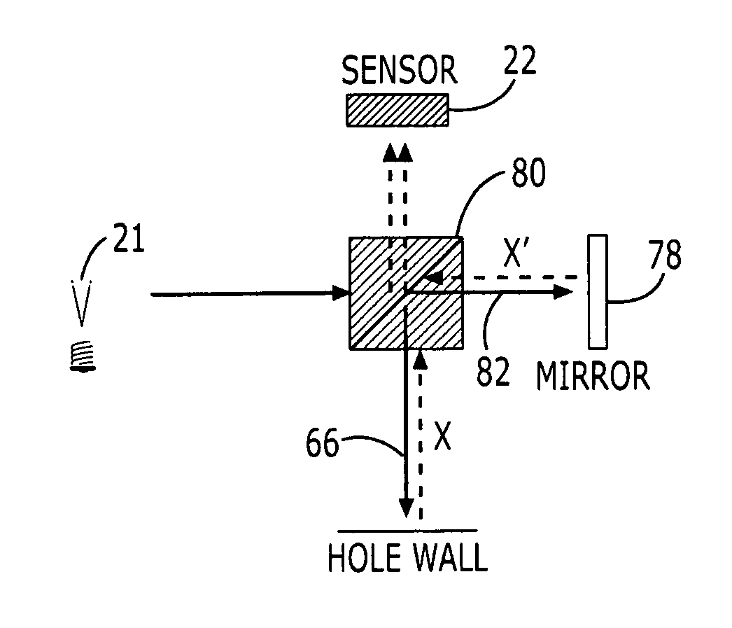
Although a few conventional tools exist that do not contact the hole while measuring the characteristics of the hole, they nevertheless fail to provide a quick, simple and accurate method to measure the characteristics of holes.
This structure is not as quick and simple of a solution to hole measurements as desired because it requires many precision parts and a complex construction to create the disc of light and construct the resulting image, which increases the likelihood of difficulties in using the probe.
The precision parts and complex construction of the conventional noncontact probes also cause repair and / or maintenance to be
time consuming.
For the reasons described above, the conventional tools to measure the dimensions of through holes do not provide the quick, simple and accurate method necessary to efficiently measure the dimensions of the thousands of holes common in many assemblies.
Without an effective manner in which to measure the dimensions of the holes, particularly the grip length, it is impossible to assure the appropriate fasteners will be selected for the holes.
The conventional tools described above require manual alignment and other user tasks before the tools can take measurements of the hole, which subjects the measurements to
human error.
In addition, the tools do not generally provide an effective means for automatic data collection.
Some of the conventional tools described above also must contact the hole wall, creating a potential for damage to the hole.
Unfortunately, even the conventional tools that do not contact the hole wall may be impractical because of the complexity of the construction.
In addition to the problems described above regarding measuring the dimensions of through holes, particularly the grip length, it is also difficult to
drill and / or measure the interface of two-step through holes using the conventional method.
A fastener inserted in a single
diameter hole exerts a large amount of pressure on the hole walls and the pressure may cause the
composite material around the hole to deteriorate or weaken over time.
Both of the
layers must be cleaned before reforming the stack to ensure no fragments of the material are caught between the
layers which could cause inaccurate alignment of the holes in the stack.
The conventional method of drilling and reaming a two-step hole is prone to
human error and
time consuming because of the numerous steps involved.
For the reasons described above in conjunction with drilling two-step holes, however, it is generally difficult to determine the locations of the interface between the material
layers with the desired accuracy.
Unfortunately, none of the conventional methods to measure grip length described above are designed to detect the interface between the materials of a stack so as to assist in drilling through the stack.

