Connecting rod

Active Publication Date: 2010-12-16
FORUM US
View PDF6 Cites 6 Cited by
  • Summary
  • Abstract
  • Description
  • Claims
  • Application Information

AI Technical Summary

Benefits of technology

[0004]In view of the problems associated with the connecting rods that are commercially available, it is my principal object to provide a new, connecting rod with two portions that can be easily disconnected from one another for replacem

Problems solved by technology

When portions of such a connecting rod wear out, the rod must be replaced in its entirety—a time-consuming and costly project.
Multi-piece rods have not, however, gained widespread acceptance s

Method used


Image

  • Connecting rod
  • Connecting rod
  • Connecting rod

Examples


Example

[0015]Similar reference characters denote corresponding features consistently throughout the drawings.

DETAILED DESCRIPTION OF THE CONNECTING ROD

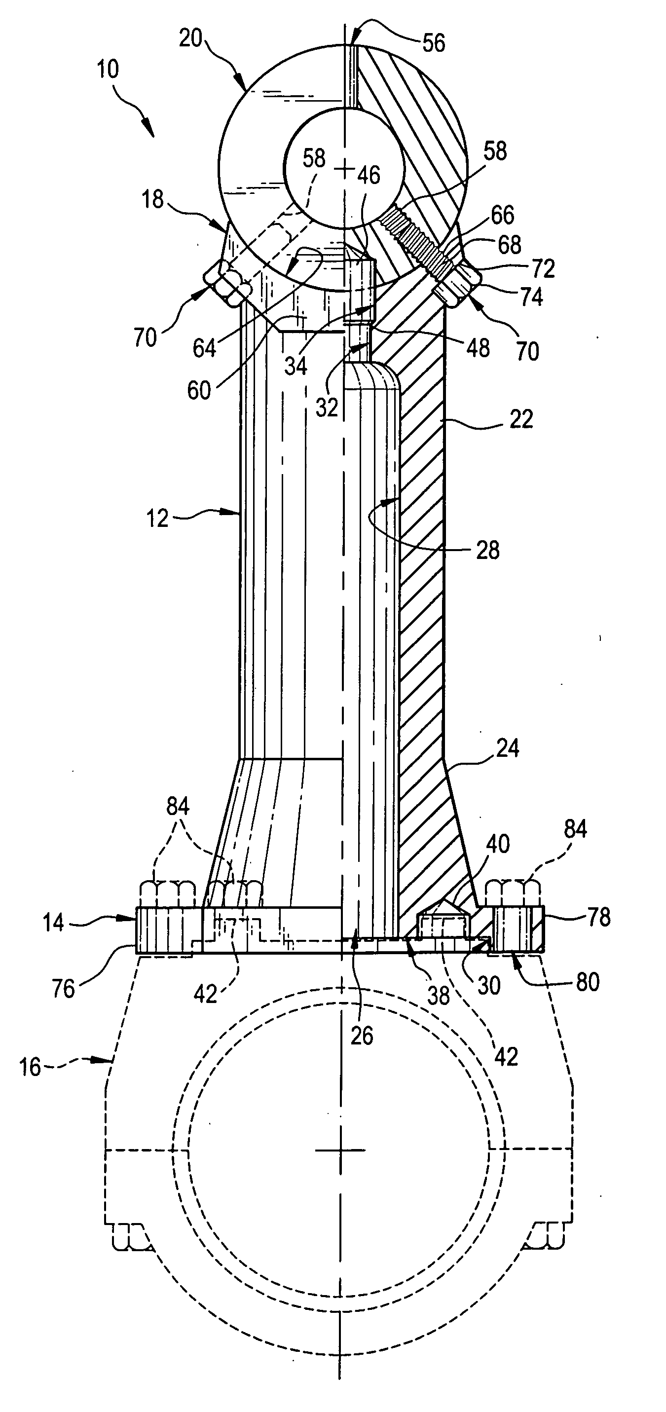
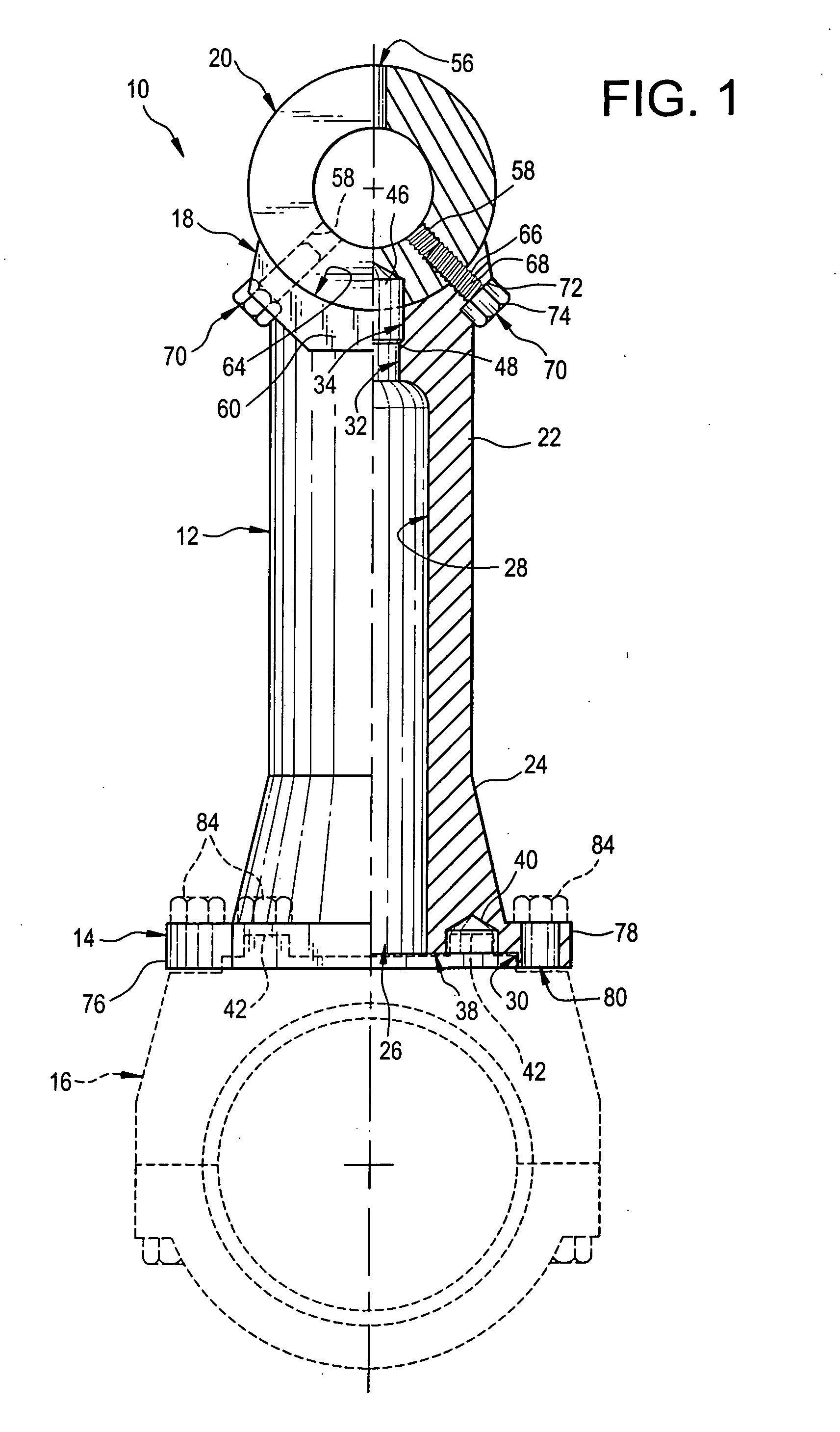
[0016]Referring now to the FIGS., a connecting rod in accordance with the present invention is shown at 10. Connecting rod 10 includes a shaft 12 having a major flange 14 affixed to its bottom end that is adapted for releasable attachment to a bearing housing 16. A minor flange 18 is affixed to the top end of shaft 12 to which a crosshead link 20 is releasably attached.

[0017]Shaft 12 is a hollow tube with an upper, cylindrical section 22 and a lower, gusset section 24 affixed to the bottom of cylindrical section 22. Cylindrical section 22 has a constant, outer diameter along its length. Gusset section 24, however, has an outer diameter that gradually increases in diameter as the distance away from cylindrical section 22 increases. Gusset section 24 serves to reinforce major flange 14 that is larger in size than minor flange 18.

[0018]Shaft 12...


PUM


Abstract

A connecting rod including a shaft, a link attached to the shaft, and a number of threaded fasteners for attaching the link to the shaft. The shaft has a major flange affixed to one of its opposed ends that can be attached to a bearing housing. A minor flange is affixed to the other of the opposed ends of the shaft and has a cylindrical concavity in its top. The minor flange has a shoulder portion and a pair of arm portions that radiate outwardly and upwardly from the shoulder portion. A link has a ring that is snugly, yet releasably, positioned within the cylindrical concavity.

Description

FIELD OF THE INVENTION[0001]This invention relates to machine elements and, more particularly, to pitmans and connecting rods.BACKGROUND OF THE INVENTION[0002]Hydraulic fracturing can increase the rate of production of oil and gas from low-permeability reservoirs. Hydraulic fracturing increases the permeability of reservoir rocks by opening channels through which oil and gas can move. During a hydraulic fracturing procedure, a fluid is pumped through a wellbore under high pressure into a subterranean reservoir where it splits or fractures the reservoir rock. A proppant, like sand, is often added to the pumped fluid and is carried in suspension into the newly formed fractures. When pumping ceases, the fractures partially close on the proppant, leaving channels for oil and gas to flow to a recovery well.[0003]High-pressure pumps are used to complete hydraulic fracturing procedures or “frac jobs.” These pumps often have connecting rods that join a crosshead to a plunger that pressurize...

Claims


Application Information

Patent Timeline
IPC IPC(8): F16C7/02
CPCF16C7/023F16C2226/60Y10T74/2142
Inventor VICARS, BERTON L.
Owner FORUM US
Why Eureka
Try Eureka