Tilt-up wall brace dolly and method of use

a wall brace and dolly technology, applied in the direction of walls, building scaffolds, building repairs, etc., can solve the problems of generating labor costs and adding construction costs to the construction

Inactive Publication Date: 2011-03-03
FINCH LARRY O
View PDF9 Cites 22 Cited by
  • Summary
  • Abstract
  • Description
  • Claims
  • Application Information

AI Technical Summary

Problems solved by technology

However, there are problems with conventional braces 210 and this conventional method of positioning the foot bracket 220.
Gouges in the surface of the floor slab 230 may require refinishing, thus, adding cost to the construction.
Consequently, a construction worker 200 must hold the lower end of the brace 210 off of the floor slab 230, generating a labor cost.

Method used


Image

  • Tilt-up wall brace dolly and method of use
  • Tilt-up wall brace dolly and method of use
  • Tilt-up wall brace dolly and method of use

Examples


Embodiment Construction

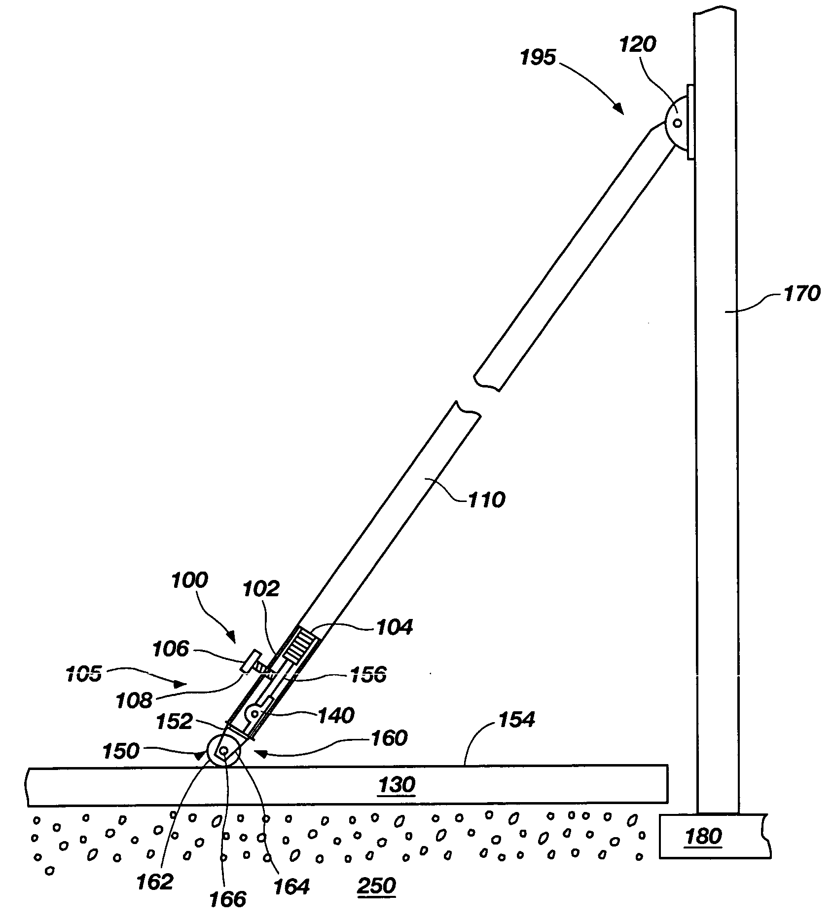
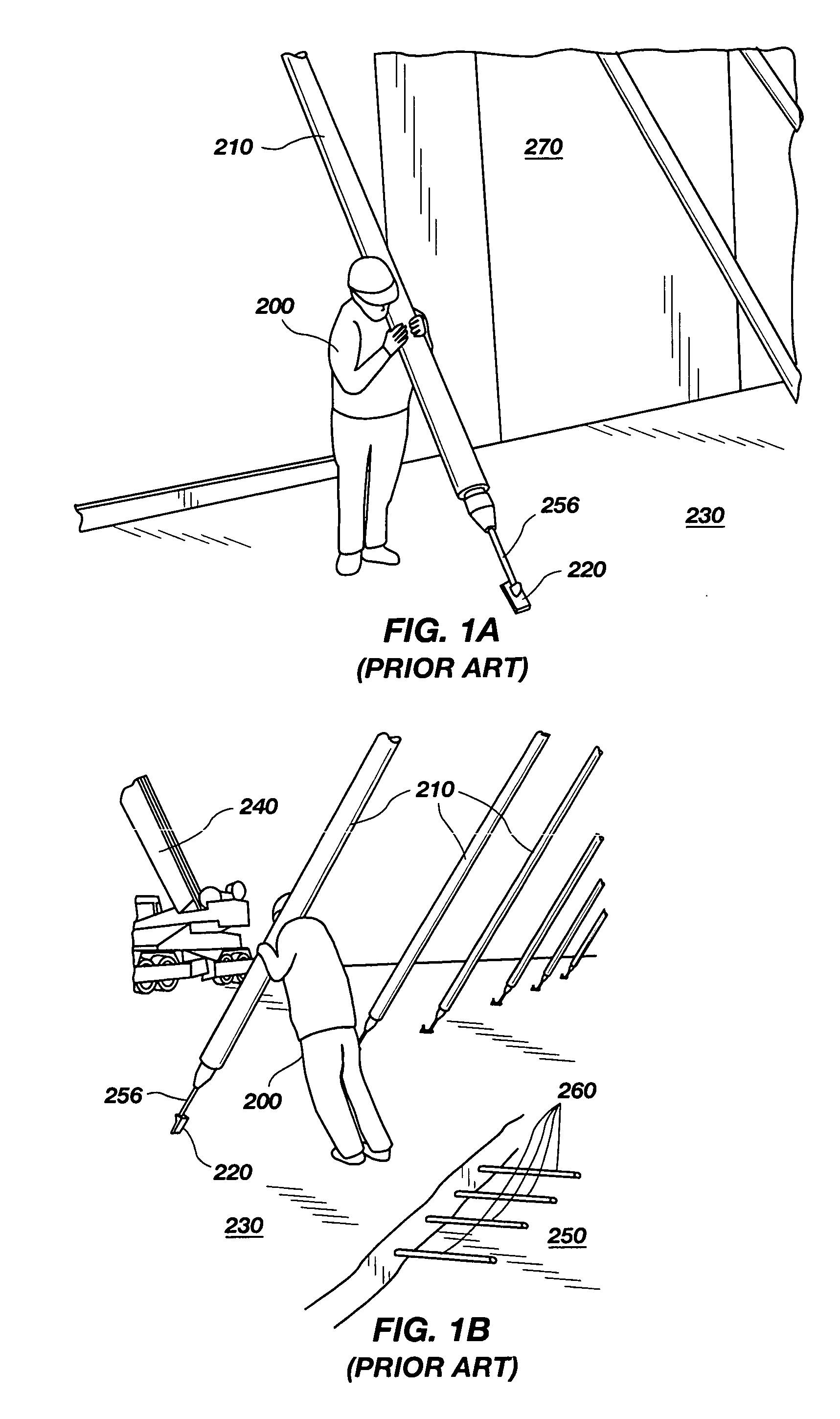
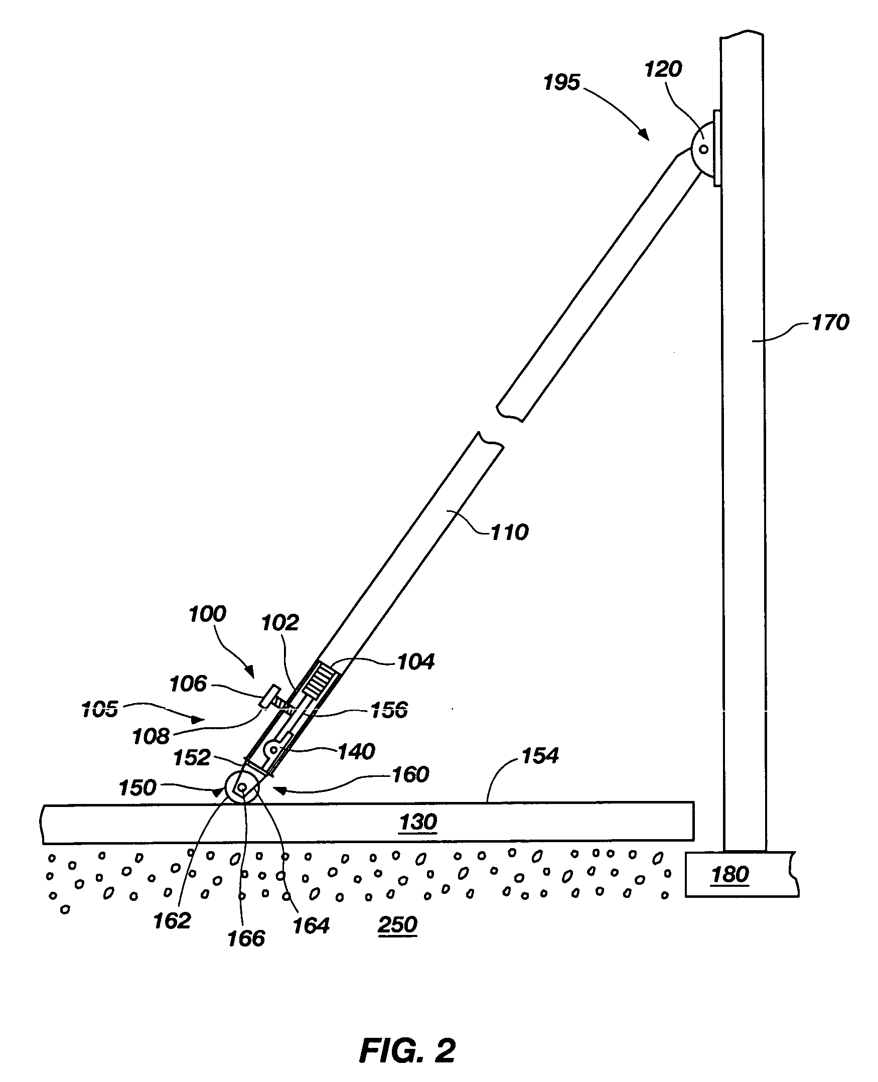
[0022]The invention is a tilt-up wall brace dolly and method of use. The embodiments of the invention are useful in the construction industry, particularly the erection and temporary bracing of tilt-up walls. Embodiments of a tilt-up wall brace dolly according to the present invention may be configured for use, or attached to, conventional tilt-up wall braces, or may be integrated into novel tilt-up wall braces. The embodiments of a tilt-up wall brace dolly illustrated and described herein are particularly useful for positioning the lower end of a tilt-up wall brace along a floor slab surface (inside of a building) or along a flat surface outside of a building during erection of a tilt-up wall. The embodiments of the invention disclosed herein may reduce construction worker fatigue. The embodiments of the invention may also reduce possible injury to construction workers during positioning of tilt-up wall braces.

[0023]FIG. 2 is a side-view of an embodiment of a tilt-up wall brace dol...


PUM


Abstract

The invention includes various embodiments of a tilt-up wall brace dolly and method of use. Tilt-up wall braces incorporating the tilt-up wall brace dolly features are also disclosed. The embodiments of the invention are useful in the construction industry, particularly the erection and temporary bracing of tilt-up walls.

Description

BACKGROUND OF THE INVENTION[0001]1. Field of the Invention[0002]This invention relates generally to construction equipment. More particularly, the invention relates to braces used to erect tilt-up concrete panels.[0003]2. Description of Related Art[0004]Tilt-up construction is a job-site form of precast concrete construction. It involves prefabricating concrete wall panels or slabs on a suitable flat surface, e.g., the building floor slab or a temporary casting slab, then lifting or “tilting” such walls up with a mobile crane with cables and carrying them to their final locations, where they are installed as vertical walls and become integral parts of the completed structure. Because the concrete walls are poured and cured horizontally on flat surfaces and subsequently lifted or “tilted” up into a vertical orientation and installed on or adjacent to a footing or floor slab to form a wall in a structure, they are variously referred to in the industry as “tilt-up walls”, “tilt-up pane...

Claims


Application Information

Patent Timeline
Patent Type & Authority Applications(United States)
IPC IPC(8): E04G21/16E04B1/38E04G21/26
CPCE04G21/26E04G21/168
Inventor FINCH, LARRY O.
Owner FINCH LARRY O
Why Eureka
Try Eureka