Pneumatic radial tire

a radial tire and pneumatic technology, applied in the direction of vehicle components, textiles and papermaking, yarn, etc., can solve the problems of increasing production cost, increasing tire weight, and inability to obtain sufficient high-speed durability in tires, so as to achieve excellent high-speed durability, increase production cost, and low rolling resistance

Inactive Publication Date: 2011-03-03
BRIDGESTONE CORP
View PDF10 Cites 2 Cited by
  • Summary
  • Abstract
  • Description
  • Claims
  • Application Information

AI Technical Summary

Benefits of technology

[0018]In the present invention, by using, as the fiber cords forming the belt reinforcing layer, single-twist cords comprising a combination of different types of fibers, the gap between the belt reinforcing layer cords and the belt layer cords can be assured without using a rubber strip or the like, and thereby a pneumatic radial tire can be realized which shows excellent high-speed durability and low rolling resistance, without causing other problems such as increase in the production cost and increase in the weight of the tire. That is, since, with a conventional hybrid cord, properties of one of the fibers are likely to appear and it is impossible to freely control the elastic modulus of the cord, the S-S curve and / or the heat shrinkage stress of the cord, only few advantages can be obtained by using different types of fibers. On the other hand, by using single twist cords as in the present invention, each different type of the cords exert its properties to enable free control of the heat shrinkage stress.

Problems solved by technology

However, with such organic fiber cords having low elastic moduli, there have been cases where sufficient high-speed durability could not be obtained in tires in recent years having increased flatness and sizes, which has been problematic.
However, with such a hybrid cord, on production of the tire, it is difficult to assure a sufficient gap between the belt reinforcing layer cords and the belt layer cords arranged in the inside thereof in the radial direction of the tire.
Therefore, in order to assure sufficient high-speed durability, a process of, for example, insertion of a rubber strip between the belt layer and the belt reinforcing layer has been necessary, which has led to increase in the production cost and increase in the weight of the tire, which has been problematic.
Further, for pneumatic radial tires, it is important to have low rolling resistance which contributes to low fuel consumption.

Method used


Image

  • Pneumatic radial tire
  • Pneumatic radial tire

Examples


example 1

Conventional Example 1, Comparative Example 1 And Examples 1-1 To 1-10

[0049]Pneumatic radial tires having a tire size of 235 / 55R17 were prepared according to the specifications shown in the tables below, and their high-speed durability and the rolling resistance were evaluated. The tensile elastic modulus of the original yarn of each fiber in tables 1 to 3 below was measured according to JIS L-1013, and represented as the value of the initial modulus calculated based on the load at an elongation of 0.1% and the load at an elongation of 0.2%.

example 2

Conventional Example 2, Comparative Example 2 And Examples 2-1 To 2-10)

[0050]Pneumatic radial tires having a tire size of 235 / 55R17 were prepared according to the specifications shown in tables 4 to 6 below, and their high-speed durability and the rolling resistance were evaluated.

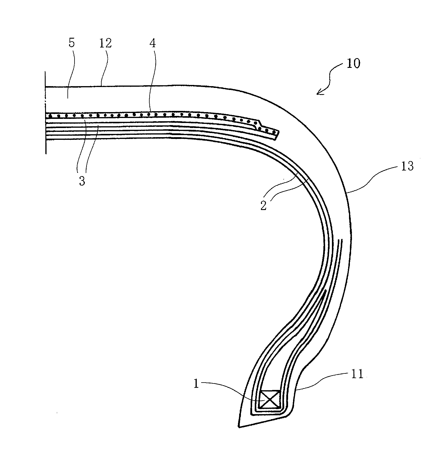
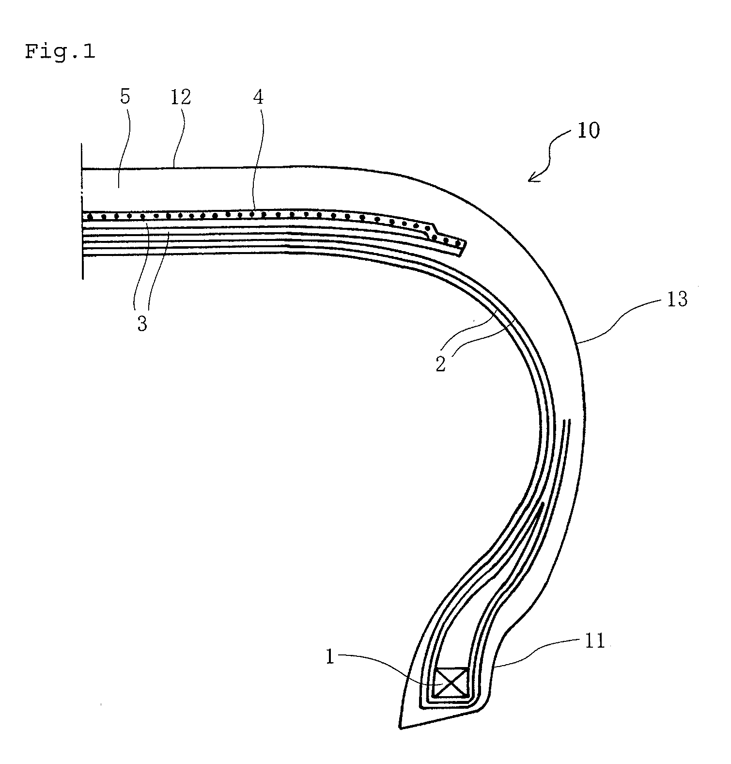
[0051]As shown in FIG. 1, each sample tire has: a bead core 1 provided in each of a left-and-right pair of bead portions 11;

[0052]two carcass plies extending from a crown portion 12 to both bead portions 11 via both side wall portions 13 and anchored to the bead cores 1, the carcass plies comprising a radial cord layer;

[0053]a belt 3 comprising two belt layers arranged in the outside of the crown portion in the radial direction;

[0054]a single belt reinforcing layer 4 arranged in the outside thereof almost in the equatorial direction of the tire; and

[0055]a tread 5 arranged in the outside thereof.

Among these, the belt 3 comprised steel cords having a 1×5 structure and a coating rubber covering them, and the...


PUM

PropertyMeasurementUnit
heat shrinkage rateaaaaaaaaaa
breaking elongationaaaaaaaaaa

Abstract

A pneumatic radial tire is provided which can realize superior high-speed durability and low rolling resistance without causing other problems such as increase in the production cost and increase in the tire weight.
A pneumatic radial tire 10 comprising: a bead core 1 provided in each of a left-and-right pair of bead portions 11; a carcass ply 2 extending from a crown portion 12 to both bead portions 11 via both side wall portions 13 and anchored to the bead cores 1, the carcass ply 2 comprising a radial cord layer; a belt 3 arranged in the outside of the crown portion in the radial direction; a belt reinforcing layer 4 arranged in the outside thereof almost in the equatorial direction of the tire; and a tread 5 arranged in the outside thereof. The fiber cords forming the belt reinforcing layer 4 are single-twist cords comprising a combination of different types of fibers.

Description

[0001]TECHNICAL FIELD[0002]The present invention relates to a pneumatic radial tire (hereinafter also simply referred to as “tire”), in particular, a pneumatic radial tire in which reinforcing cords used in the belt reinforcing layer are improved.BACKGROUND ART[0003]In general, in a pneumatic radial tire for high-speed driving, a belt reinforcing layer covering at least the both edge portions of a belt layer is arranged in the outside of the belt layer in the radial direction of the tire. This belt reinforcing layer exerts an effect of enhancing the high-speed durability of the tire by suppressing, by a hoop effect, rising of the both edge portions of the belt layer caused by the centrifugal force during high-speed rotation of the tire.[0004]Conventionally, as the cords constituting this belt reinforcing layer, organic fiber cords having a double-twist structure have been mainly used, which organic fiber cords were produced by twisting a plurality of first-twisted bundles of wires o...

Claims


Application Information

Patent Timeline
Patent Type & Authority Applications(United States)
IPC IPC(8): B60C9/18
CPCB60C9/0042B60C9/2009B60C9/005D02G3/48B60C9/22
Inventor ZUIGYO, YUGO
Owner BRIDGESTONE CORP
Why Eureka
Try Eureka