Pneumatic tires for vehicles with straps

A technology for pneumatic tires and vehicles, applied to the reinforcement layer of pneumatic tires, vehicle parts, tire parts, etc. Small, reduced rolling resistance, good high-speed durability

Active Publication Date: 2019-05-21
CONTINENTAL REIFEN DEUTSCHLAND GMBH
View PDF6 Cites 0 Cited by
  • Summary
  • Abstract
  • Description
  • Claims
  • Application Information

AI Technical Summary

Problems solved by technology

However, there is a conflict of objectives here: high modulus materials with too low elongation at break cannot be constructed on an expansion drum

Method used


Image

  • Pneumatic tires for vehicles with straps
  • Pneumatic tires for vehicles with straps

Examples


Embodiment Construction

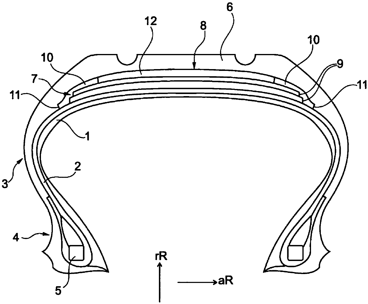
[0035] figure 1 A radial cross section through a vehicle pneumatic tire for passenger cars is shown. The main components that make up the pneumatic vehicle tire shown are: a largely air-impermeable inner layer 1, a carcass 2 (the carcass starts in a conventional manner from the apex region of the pneumatic tire for vehicles, passes through the sides 3, and ends in into the bead area 4 and anchored in the bead area by coiling the stretch-resistant bead core 5), the shaped tread 6 located radially outside the carcass, and between the tread 6 and the tire Arranged between the bodies 2 is a cord strip 7 comprising two reinforcing carrier layers, which cord strip is covered radially on the outside with a belt band comprising a band layer 8 . The band layer covers the cord belt edges 9 and contains reinforcing carriers coiled in parallel along the axial width in the circumferential direction of the vehicle pneumatic tire.

[0036] The cuff layer 8 comprises in its axial extension...


PUM

PropertyMeasurementUnit
elongation at breakaaaaaaaaaa

Abstract

Pneumatic vehicle tyres which have a bandage ply (8) comprising two lateral portions (10) and a center portion (12) in the axial extension, wherein each lateral portion (10) has at least one hybrid reinforcement, and wherein the center portion (12) has at least one reinforcement which has a lower modulus of elasticity than the hybrid reinforcements of the lateral portions (10), in each case measured as per ASTM D885M at an elongation of 3%. It is the object of the invention to provide a tyre with reduced rolling resistance and good high-speed characteristics with reliable producibility. This is achieved in that the hybrid reinforcement is a hybrid cord made of at least one low-modulus thread and one high-modulus thread twisted together, and in that the hybrid reinforcement has a fineness of at most 550 dtex, preferably at most 500 dtex, particularly preferably at most 460 dtex, and in that the reinforcement of the center portion (12) has a fineness of at most 1100 dtex, preferably at most 600 dtex, particularly preferably at most 500 dtex.

Description

technical field [0001] The present invention relates to a vehicle pneumatic tire having a carcass, a formed tread, a cord band and a single or multi-layer belt band covering the cord band, the belt The band has a plurality of reinforcing carriers running in the circumferential direction of the tyre, wherein at least one band layer of the band band comprises in its axial extension two side sections and in the two side areas A middle section arranged between the sections, the side sections respectively comprise an axial edge of the cuff layer, wherein each side section has at least one hybrid reinforcement carrier and wherein the middle section has at least one reinforcement The carrier, respectively measured at 3% elongation according to ASTM D885M, has a lower modulus of elasticity than the mixed reinforcing carrier of the side sections. Background technique [0002] In order to avoid tire heaving due to the centrifugal forces generated during driving operation (especially ...

Claims


Application Information

Patent Timeline
Patent Type & Authority Patents(China)
IPC IPC(8): B60C9/00B60C9/18
CPCB60C9/0042B60C9/005B60C9/22B60C2009/0078B60C2009/2223B60C2009/2257B60C2009/2261
Inventor 沃尔夫冈·雷泽
Owner CONTINENTAL REIFEN DEUTSCHLAND GMBH
Why Eureka
Try Eureka