Optical assembly, backlight unit and display apparatus thereof
a backlight unit and optical assembly technology, applied in the direction of static indicating devices, lighting and heating devices, instruments, etc., can solve the problem that the backlight unit cannot produce a slim lcd device, and achieve the effect of improving the image quality of the display pictur
- Summary
- Abstract
- Description
- Claims
- Application Information
AI Technical Summary
Benefits of technology
Problems solved by technology
Method used
Image
Examples
first embodiment
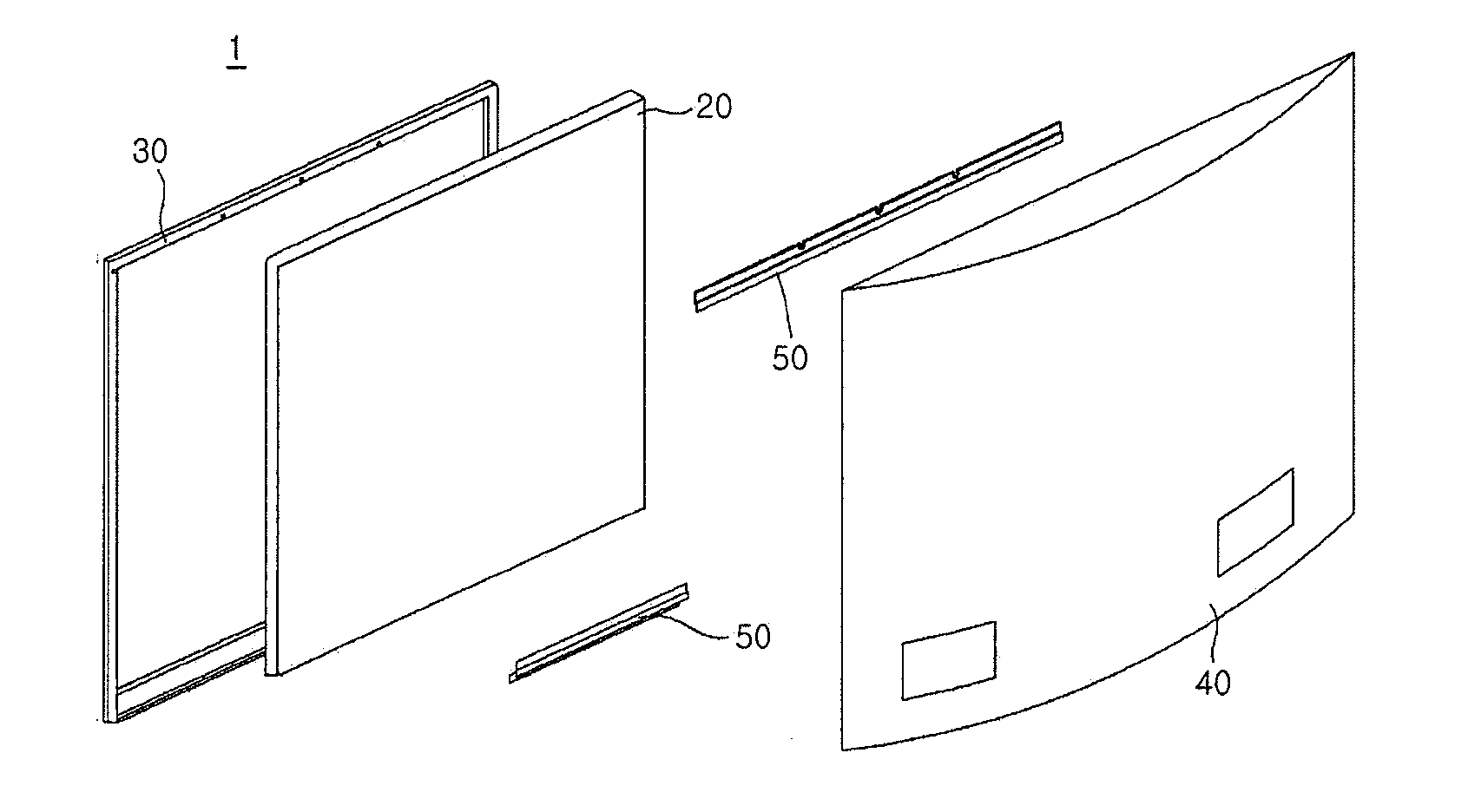
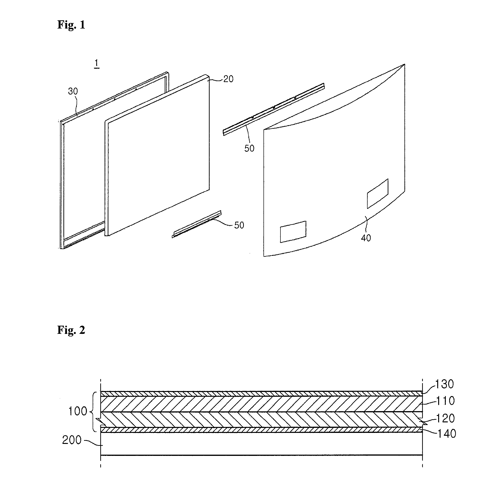
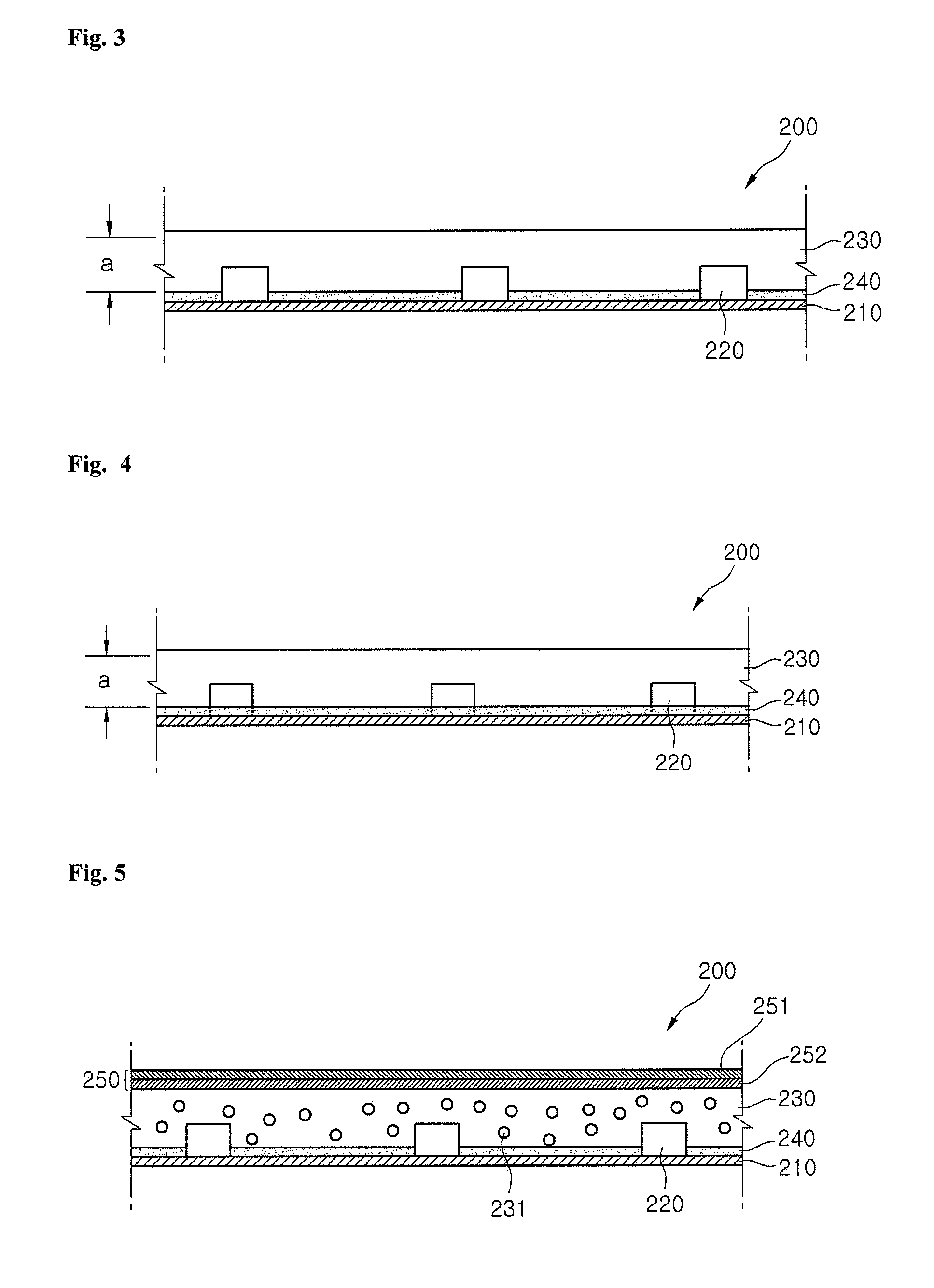
[0058]FIG. 3 is a cross-sectional view illustrating a configuration of a backlight unit according to the present invention. The illustrated backlight unit 200 can include a first layer 210, light sources 220, a second layer 230, and a reflection layer 240. The light sources 220 in the backlight unit 200 are formed below the display panel 100 for providing light throughout the display panel 100 as shown in FIGS. 1 and 2.
[0059]Referring to FIG. 3, the plurality of light sources 220 are formed on the first layer 210 and the second layer 230 is disposed on the top of the first layer 210 to cover the plurality of light sources 220. Preferably the second layer 230 completely encapsulates the light sources 220 formed on the first layer 210, but in another example, thes second layer 230 can cover only certain portions / sides of the light sources 220 formed on the first layer 210.
[0060]The first layer 210 may be a substrate on which the plurality of light sources 220 are mounted. An electrode...
second embodiment
[0079]FIG. 5 is a cross-sectional view illustrating a configuration of a backlight unit according to the present invention. Description of the same components of the backlight unit 200 shown in FIG. 5 as those explained by referring to FIGS. 2 and 3 will now be omitted.
[0080]Referring to FIG. 5, the plurality of light sources 220 can be mounted on the substrate 210 and the resin layer 230 can be disposed on the top of the substrate 210 to cover the light sources 230 entirely or partially. Meanwhile, the reflection layer 240 can be formed between the substrate 210 and the resin layer 230, e.g., on the top of the substrate 210.
[0081]Further, as shown in FIG. 5, the resin layer 230 can include a plurality of scattering particles 231 and the scattering particles 231 can more widely diffuse the light emitted from the light sources 220 by scattering or refracting the incident light.
[0082]The scattering particles 231 can be made of a material having a refractive index different from the ma...
third embodiment
[0095]FIG. 6 is a cross-sectional view illustrating a configuration of a backlight unit according to the present invention, and depicts an example of the light sources 220 inserted within the indentations / holes defined through the reflections layer 240. Description of the same components of the backlight unit 200 shown in FIG. 6 as those explained by referring to FIGS. 2 to 5 will now be omitted.
[0096]Referring to FIG. 6, each of the plurality of light sources 220 provided in the backlight unit 200 has the light emitting surface on the side surface thereof and can emit light in a lateral direction, e.g., a direction in which the substrate 210 or the reflection layer 240 extends above the substrate 210.
[0097]For example the plurality of light sources 220 can be configured by using the side view-type LED packages. As a result, it is possible to reduce a limitation that the light source 220 is observed as a hot spot on a screen, and it is possible to produce a slim backlight unit 200 a...
PUM
 Abstract
Description
Claims
Application Information
 - R&D
- Intellectual Property
- Life Sciences
- Materials
- Tech Scout
- Unparalleled Data Quality
- Higher Quality Content
- 60% Fewer Hallucinations
Browse by: Latest US Patents, China's latest patents, Technical Efficacy Thesaurus, Application Domain, Technology Topic, Popular Technical Reports.
© 2025 PatSnap. All rights reserved.Legal|Privacy policy|Modern Slavery Act Transparency Statement|Sitemap|About US| Contact US: help@patsnap.com


