
Joint instrument support assembly

Inactive Publication Date: 2011-03-03
REMARKABLE
View PDF12 Cites 3 Cited by
  • Summary
  • Abstract
  • Description
  • Claims
  • Application Information

AI Technical Summary

Benefits of technology

In view of the foregoing, the invention provides a joint instrument support assembly to make the orientation adjustment of an instrument on the support frame more quickly.

Problems solved by technology

Therefore, one cannot arbitrarily change the angle and fix it.
It is very time-consuming.
It is still quite inconvenient.
Consequently, both of the above-mentioned two conventional instrument support assemblies have the problem of inconvenient in adjustments.

Method used


Image

  • Joint instrument support assembly
  • Joint instrument support assembly
  • Joint instrument support assembly

Examples


first embodiment

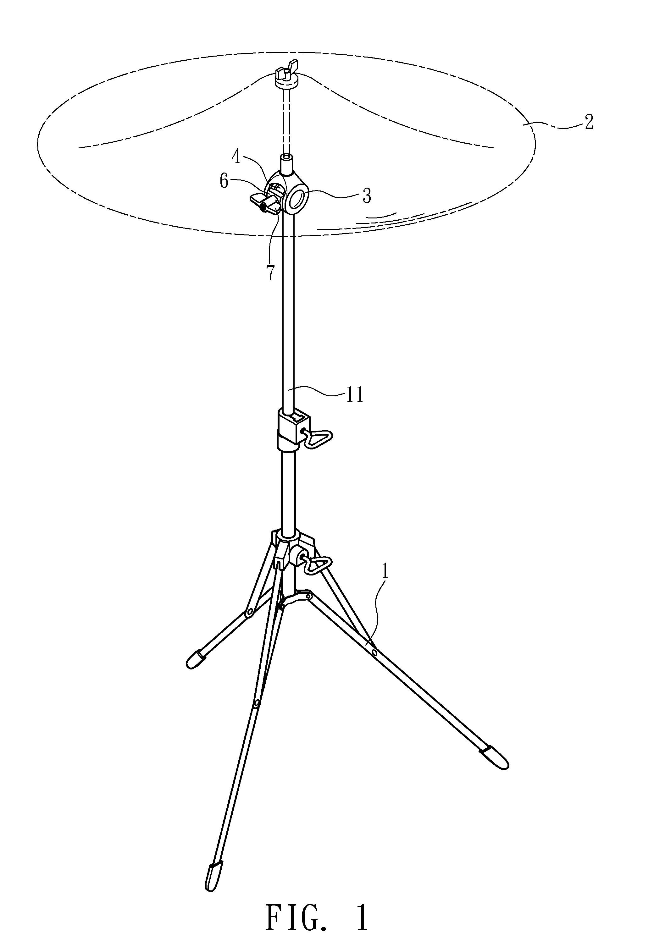
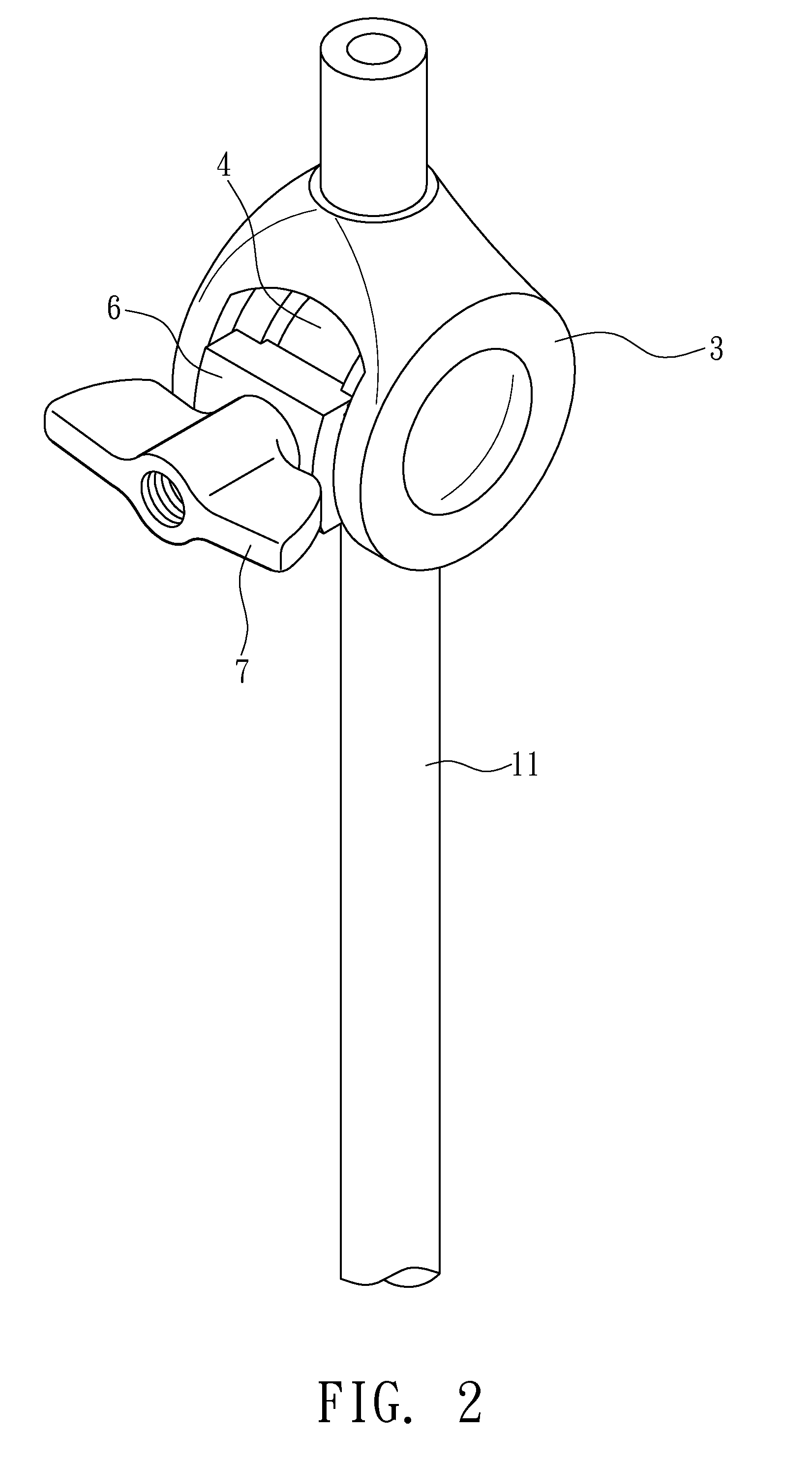
Please refer to FIGS. 1 to 5 for the invention. This is only an illustration and should not be used to restrict the scope of the invention.

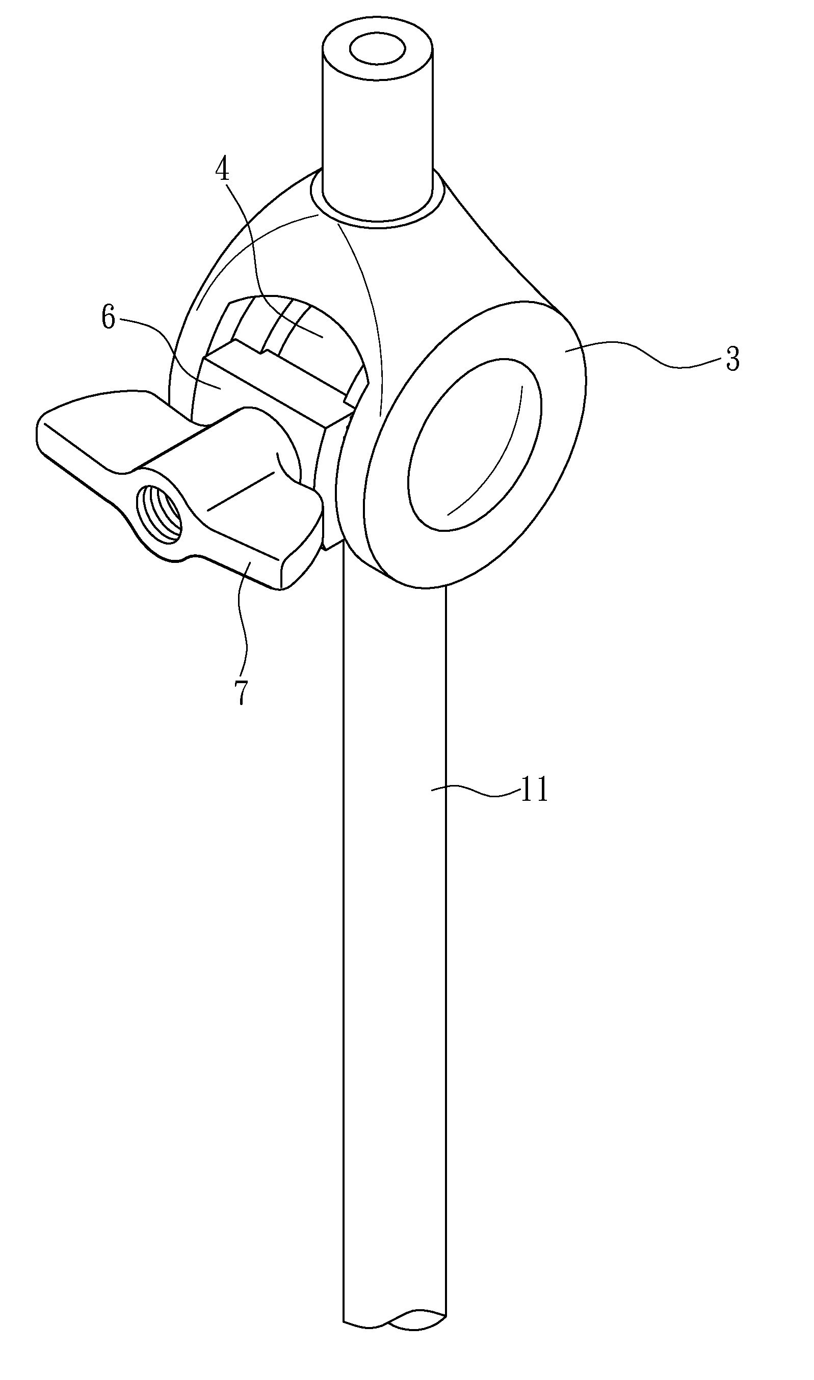
This embodiment provides a joint instrument support assembly for a vertical support frame 1 to fix and adjust a cymbal 2. It includes: a rotating elbow 3, a cylindrical rotating block 4, a sliding block 5, a pad 6, and a fastening element 7.

Both sides of the rotating elbow 3 have an ear part 31, 32, respectively. A groove 33 is formed between the two ear parts 31, 32. The ear part 31 has a circular hole 34 to communicate with the groove 33. Both ear parts 31, 32 are formed respectively with a circular wall 35 toward the groove 33. The outer edges 351 of the circular walls 35 are symmetric and have an outer diameter larger than the circular hole 34.

The cylindrical rotating block 4 goes from the circular hole 34 of the ear part 31 through the groove 33 and urges against the other ear part 32. It is restricted to rotate within the two circular walls...


PUM


Abstract

A joint instrument support assembly is disclosed. Both sides of a rotating elbow have an ear part, respectively. A groove is formed between the two ear parts. One ear part communicates with the groove via a circular hole. The two ear parts have a circular wall toward the groove, respectively. A rotating block is disposed in the rotating elbow. A rod goes through the rotating block. A limiting element locks on the rod and positions in the axle hole to rotate with respect to the rotating block. A sliding block having a through hole and an outer thread part is disposed in an accommodating room. A pad is mounted on the outer thread part and strides across the outer edges of the two circular walls. A fastening element locks onto the outer thread part outside the pad.

Description

BACKGROUND OF THE INVENTION1. Field of InventionThe invention relates to a joint instrument support assembly and, in particular, to a structure that is disposed on the base of an instrument support and connects to the instrument.2. Related ArtAs shown in FIG. 21, a conventional instrument support assembly has a rotating elbow 80 connecting a cymbal 81 to the support frame 82 for adjusting the orientation thereof The rotating elbow 80 has an elbow base 801 fixed to the rod 82 of the support frame. A rotating block 802 connects to the cymbal 81. The elbow base 801 and the rotating block 802 engage with each other by teeth. When they are released, one can adjust the angle between the cymbal 81 and the support frame. When they are fastened, the angle is fixed.However, in the above-mentioned instrument support assembly, to adjust the angle of the rotating elbow 80 relative to the elbow base 801, one has to engage the teeth of the rotating block 802 and the elbow base 801 in order to fix ...

Claims


Application Information

Patent Timeline
IPC IPC(8): F16C11/10G10D13/063
CPCG10D13/026Y10T403/32106G10D13/06G10D13/28G10D13/02G10D13/063
Inventor CHANG, MING-YI
Owner REMARKABLE
Learn More