Moulding Chamber Arrangement for a Mould-String Plant

Inactive Publication Date: 2013-06-27
DISA IND
View PDF6 Cites 0 Cited by
  • Summary
  • Abstract
  • Description
  • Claims
  • Application Information

AI Technical Summary

Benefits of technology

The present invention provides a molding chamber arrangement that allows for more flexibility in the size of the produced molds without affecting the flow of sand. Additionally, it is easy to adjust the height and requires minimal manual work.

Problems solved by technology

A problem with a moulding chamber of this type is that it is not possible to use pattern plates that vary in the height.
In connection with reduction of the height of the moulding chamber, the insertion of an adaptor plate on the upper wall of the moulding chamber increases the distance between the sand feed system and the moulding chamber, whereby the sand flow into the moulding chamber will be affected unfavourably.
Moreover, it is very laborious and time consuming to insert or remove adaptor plates in the chamber ceiling because it requires the movement of very heavy components (adaptor plates of the above mentioned kind weigh several hundreds of kg), and inevitable residue deposits of sand in the sand feed system will also leak into the moulding chamber during the insertion or removal of the adaptor plates.

Method used


Image

  • Moulding Chamber Arrangement for a Mould-String Plant
  • Moulding Chamber Arrangement for a Mould-String Plant
  • Moulding Chamber Arrangement for a Mould-String Plant

Examples


Embodiment Construction

[0058]The present invention will now be described more fully hereinafter with reference to the accompanying drawings, in which exemplary embodiments of the invention are shown. The invention may however be embodied in different forms and should not be construed as limited to the embodiments set forth herein. Rather, these embodiments are provided so that this disclosure will be thorough and complete, and will fully convey the scope of the invention to those skilled in the art. Like reference numerals refer to like elements throughout. Like elements will thus not be described in detail with respect to the description of each figure.

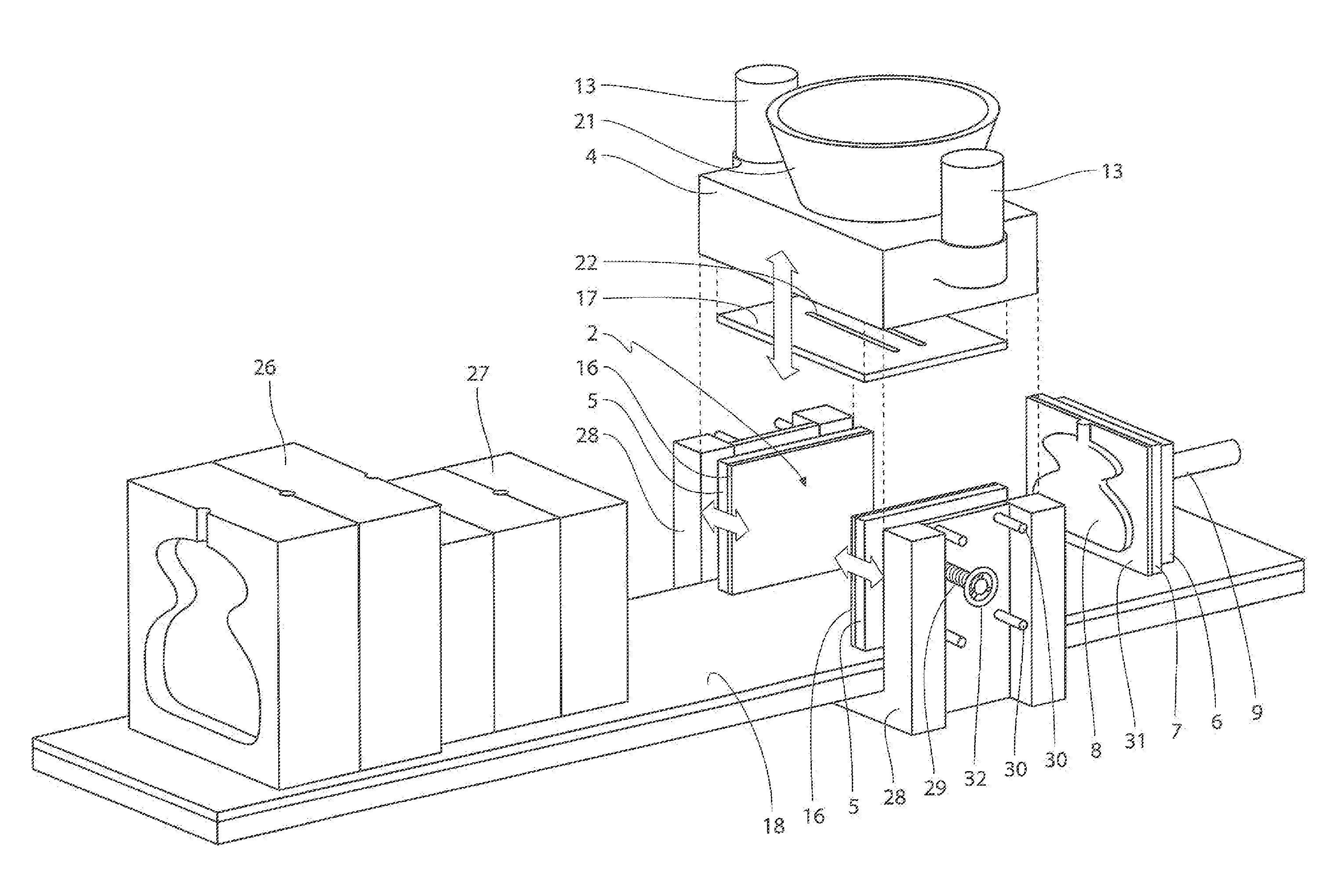
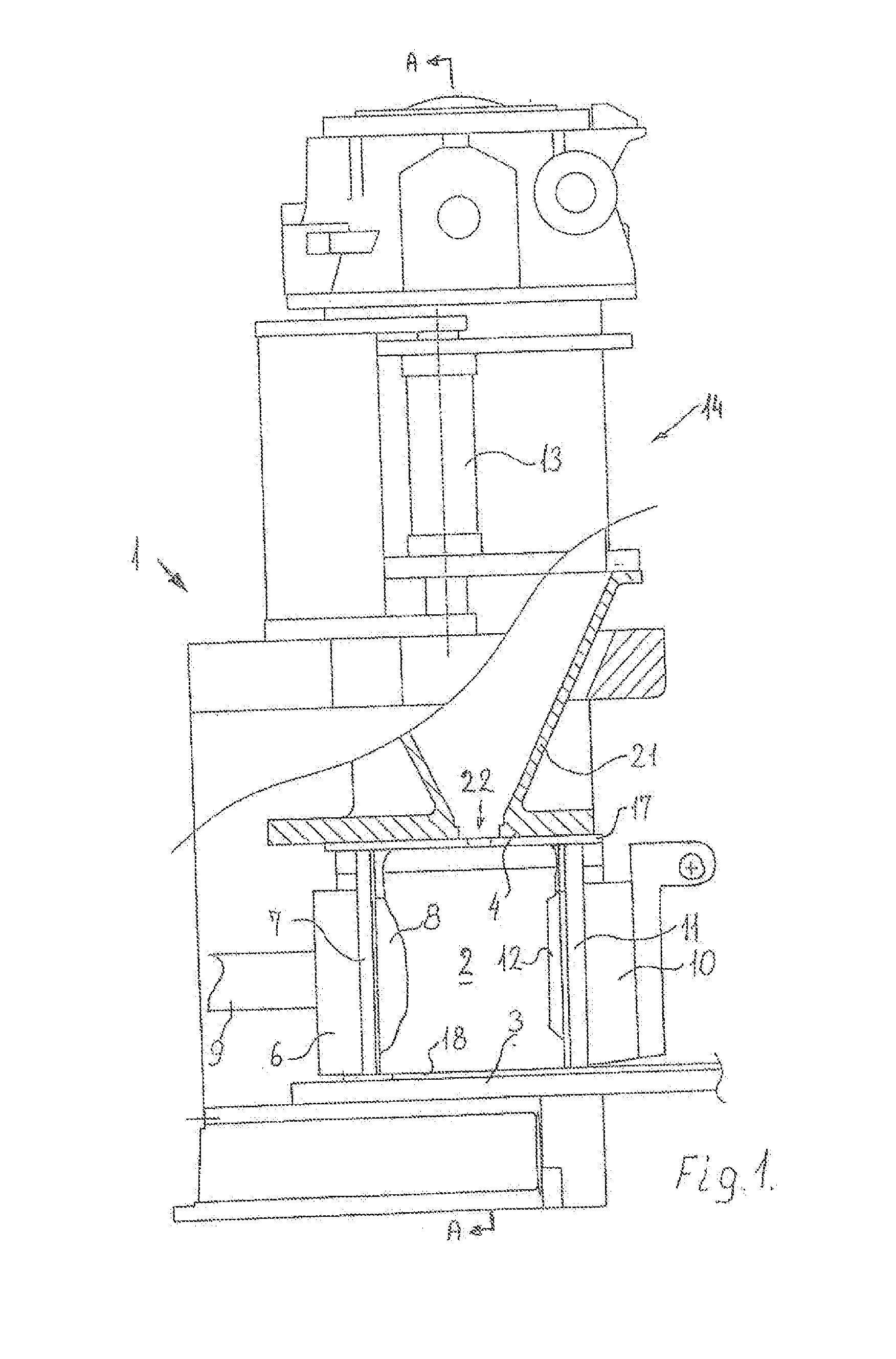
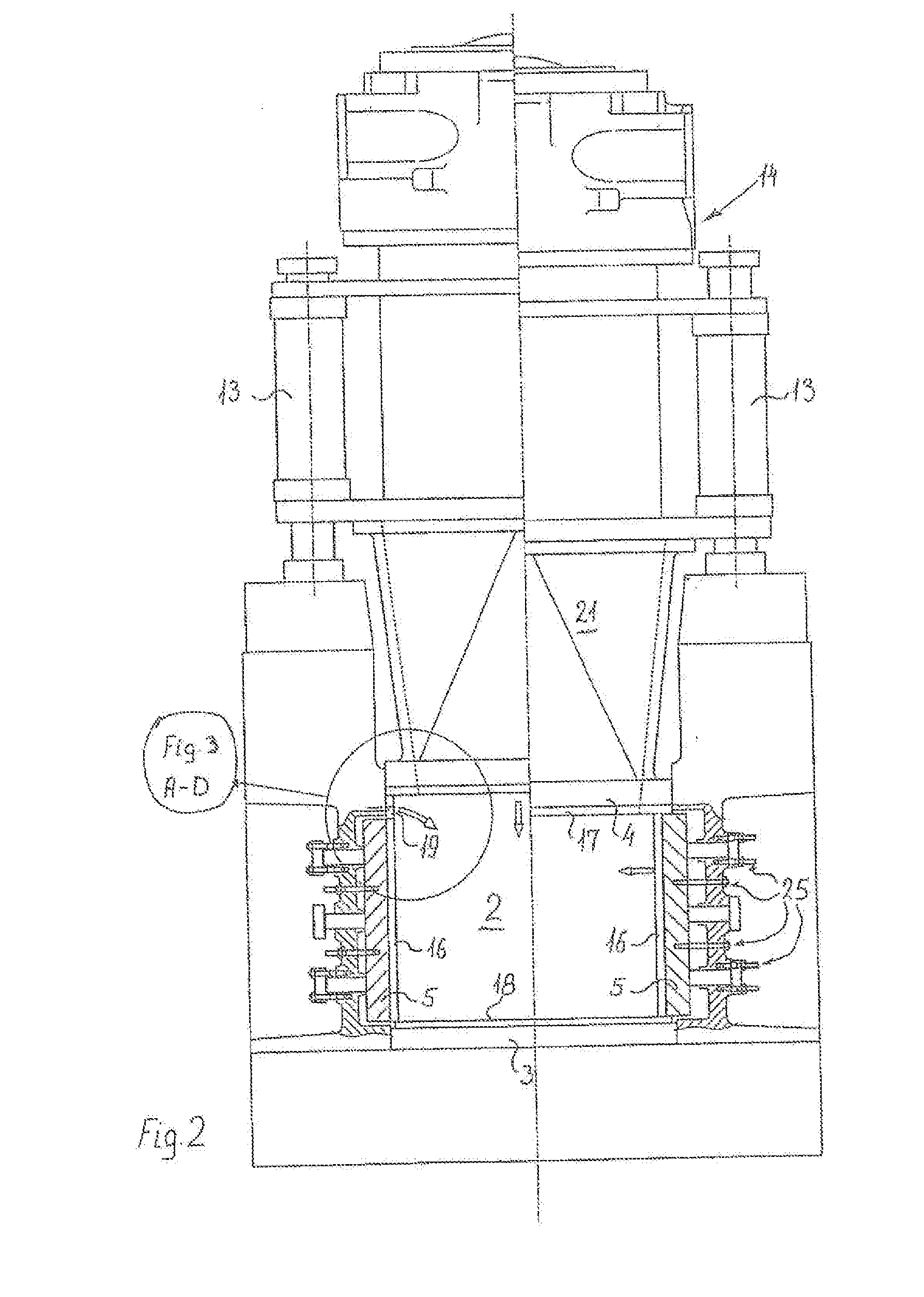
[0059]The moulding chamber arrangement shown in FIG. 1 comprises a sand-feed system 14 for filling sand into the moulding chamber 2, said moulding chamber 2 being delimited by two patterns 8, 12 and a chamber bottom 3 and two chamber side walls 5, 24 shown in FIGS. 2-5 and a chamber ceiling 4.

[0060]In the illustrated mould-string plant, the pressure patter...


PUM

PropertyMeasurementUnit
Thicknessaaaaaaaaaa
Sizeaaaaaaaaaa
Flexibilityaaaaaaaaaa

Abstract

Moulding chamber arrangement (1) for a mould-string plant comprising a moulding chamber (2) formed by a chamber bottom (3), a chamber ceiling (4) provided with one or more sand filling openings (22) communicating with a sand-feed system (14), two chamber side walls (5), a pressure plate (6) provided with an exchangeable pressure pattern plate having a pressure pattern (8) and being connected to a movement mechanism (9), a swingable plate (10) provided with an exchangeable swing pattern plate having a swing pattern (12) and being mounted for translational and swinging movement in order to open and close the moulding chamber (2), allowing the pressure plate (6) to expel the produced moulds, and further comprising means (13) for vertically moving the chamber ceiling (4) and sand-feed system (14) in unison, or the chamber bottom (3), or both, relative to the remainder of the moulding chamber arrangement (1), thereby changing the height of the moulding chamber. By this arrangement, the flexibility of the size of the produced moulds, especially the heights of the produced moulds, can be adjusted without changing the geometry of the sand feed system above the moulding chamber in a time-saving manner.

Description

TECHNICAL FIELD[0001]The present invention relates to a moulding chamber arrangement for a mould-string plant of the kind set forth in the preamble to claim 1.BACKGROUND ART[0002]In moulding chambers for mould-string plants of this kind it is known to provide variable sizes of the moulding chamber by making the side walls of the moulding chamber movable and adjusting the positioning of the side walls by means of a hydraulic system. A moulding chamber of this type is known from EP 1 149 645 A1. A problem with a moulding chamber of this type is that it is not possible to use pattern plates that vary in the height.[0003]Furthermore, WO 2009 / 074838 discloses a moulding chamber arrangement for a mould-string plant, in which a variable size of the moulding chamber is provided by using adaptor plates for reducing the size of the moulding chamber. In connection with reduction of the height of the moulding chamber, the insertion of an adaptor plate on the upper wall of the moulding chamber i...

Claims


Application Information

Patent Timeline
IPC IPC(8): B29C37/00
CPCB22C9/20B29C37/005B22C11/10
Inventor JOHANSEN, JORNNIELSEN, RAHLF HENNING
Owner DISA IND
Why Eureka
Try Eureka