Environmental control for HVAC system

a technology of environmental control and hvac system, applied in the direction of heating types, instruments, static/dynamic balance measurement, etc., can solve the problems of reducing the reliability and responsiveness of the real-time system, affecting the operation of the system, and affecting the reliability of the real-time system. , to achieve the effect of reducing the reliability and responsiveness of the real-time system, affecting the operation of the system, and affecting the resolution of the operation of the problem

Active Publication Date: 2011-03-03
OPTIMUM ENERGY
View PDF15 Cites 16 Cited by
  • Summary
  • Abstract
  • Description
  • Claims
  • Application Information

AI Technical Summary

Benefits of technology

[0007]The system may solve at least four problems. First, programming the complex logic required to optimize HVAC systems in the BAS reduces reliability and responsiveness of the real-time system. Second, modification to the programming require

Problems solved by technology

First, programming the complex logic required to optimize HVAC systems in the BAS reduces reliability and responsiveness of the real-time system.
Second, modification to the progr

Method used


Image

  • Environmental control for HVAC system
  • Environmental control for HVAC system
  • Environmental control for HVAC system

Examples


Embodiment Construction

[0015]In the following description, certain specific details are set forth in order to provide a thorough understanding of various embodiments of the invention. However, one skilled in the art will understand that the invention may be practiced without these details. In other instances, well-known structures associated with HVAC systems and individual HVAC components, building climate or environmental control systems, building automation systems (BASs) and various climate control or environmental control processes, parameters, and operations thereof have not necessarily been shown or described in detail to avoid unnecessarily obscuring descriptions of the embodiments of the invention.

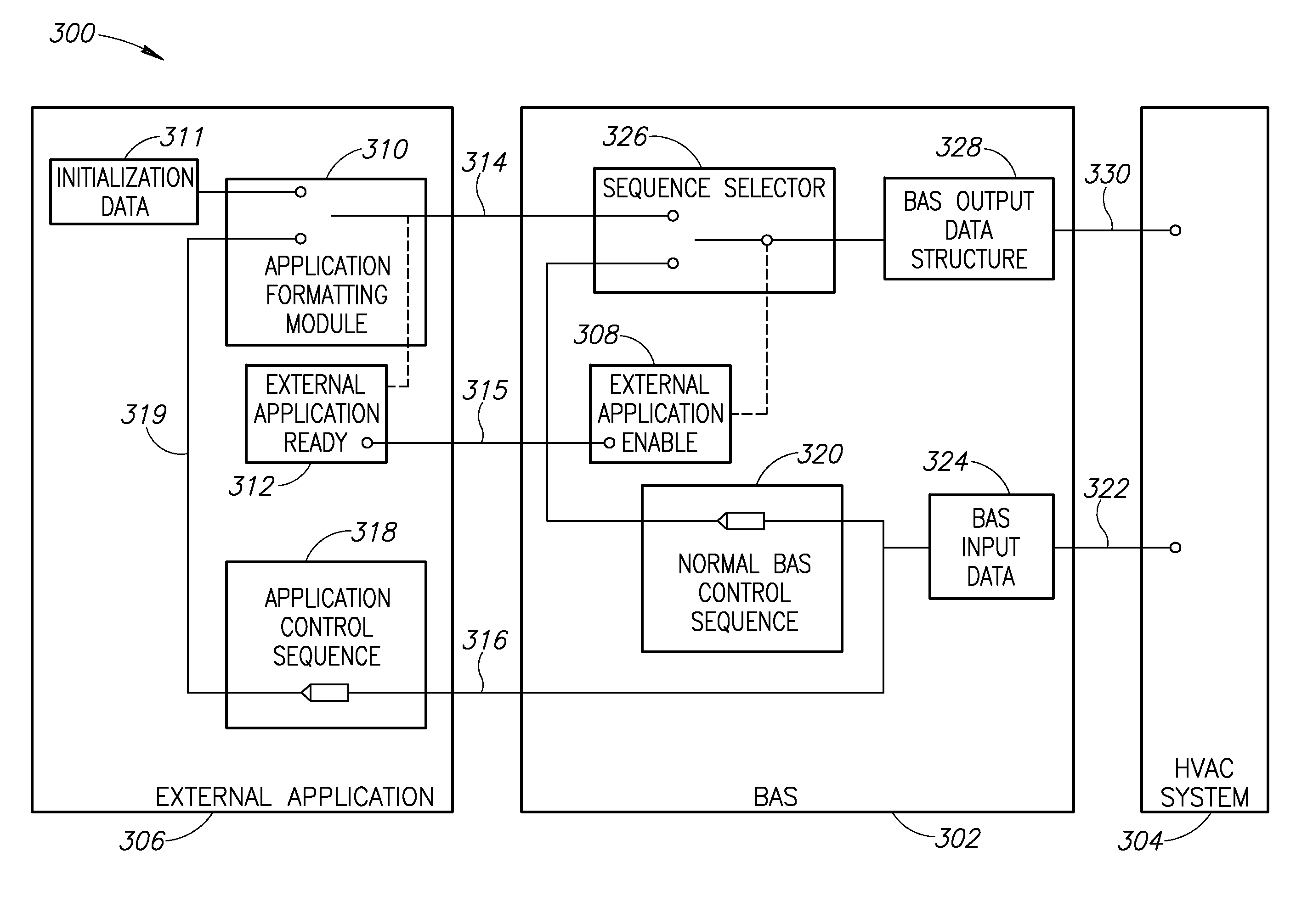
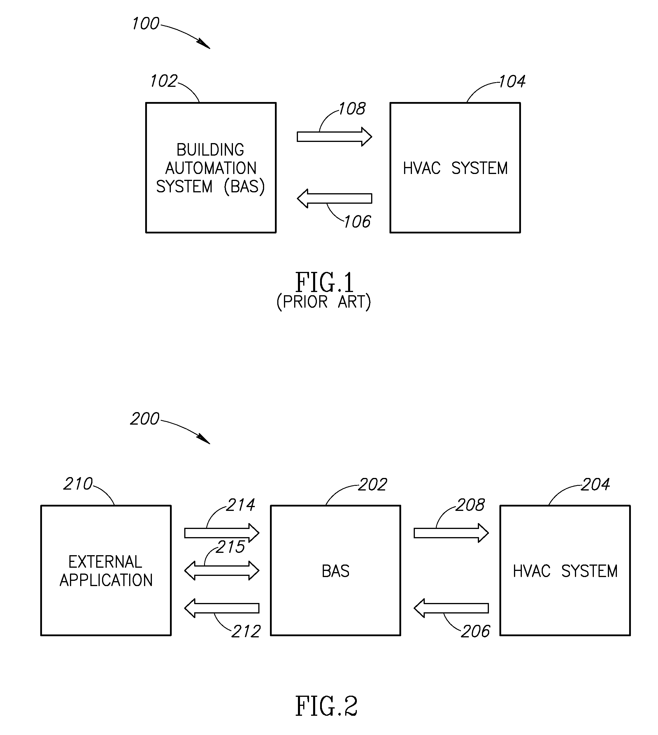
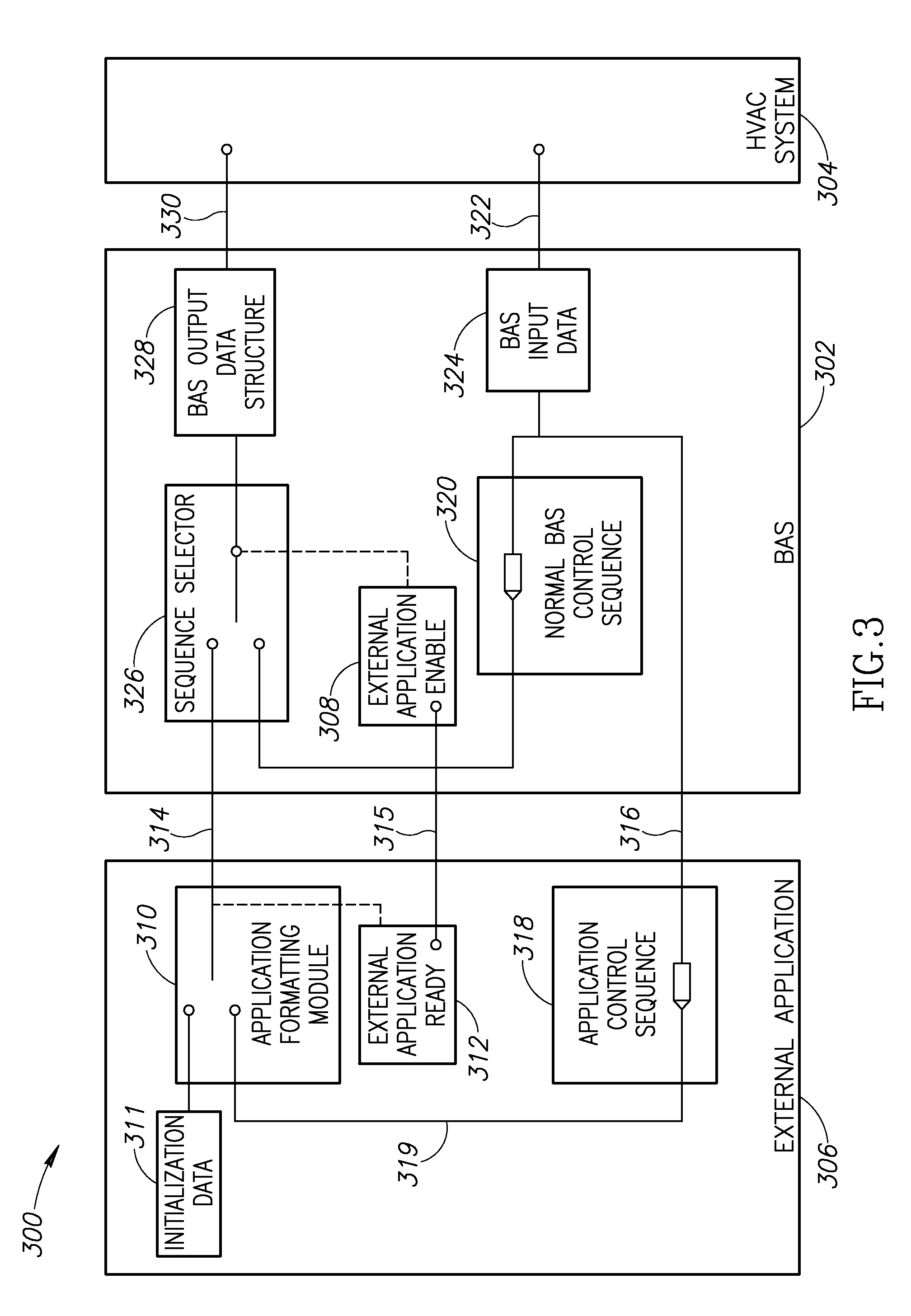
[0016]One objective of the invention is to separate energy optimization computation from equipment control functions by externally interacting with the BAS of an HVAC system. In one embodiment, an external application is located in a global control device, but could be housed in another hardware device ...


PUM


Abstract

A system for controlling energy consumption in a building having a heating, ventilation and air-conditioning (HVAC) which includes using an external application to perform HVAC energy consumption optimization algorithms and other external energy control functions and transmit application control data to a building automation system (BAS), which in turn provides hardware level equipment control for the HVAC system. The external application evaluates equipment data received from the HVAC system by way of the BAS and processes these equipment data to provide application control data back to the BAS. The application control data are calculated to achieve a desired operating efficiency for the HVAC system.

Description

PRIORITY CLAIM[0001]This application claims priority to the U.S. Provisional Patent Application No. 61 / 234,199 filed on Sep. 2, 2009, the subject matter of which is incorporated by reference herein in its entirety.FIELD OF THE INVENTION[0002]The present invention generally relates to systems and methods for externally controlling energy consumption of a heating, ventilation, and air conditioning (HVAC) system.BACKGROUND OF THE INVENTION[0003]Controlling the energy consumption of a building, and in particular the energy consumption of an HVAC system, has been achieved through a building automation system (BAS) having software executable algorithms that incorporate numerical constant values corresponding to equipment operating characteristics. FIG. 1 shows a BAS interacting with an HVAC system in which real-time operating conditions within the HVAC system are sent to the BAS while control settings are received.[0004]The equipment of the HVAC system may include, but is not limited to, ...

Claims


Application Information

Patent Timeline
IPC IPC(8): G05D23/19
CPCF24F11/0009H04L12/2803F24F2011/0068F24F11/30F24F11/56F24F11/46F24F11/63F24F2140/00
Inventor DEMPSTER, IANERPELDING, BENMATTHYS, CLARKHANNA, JAMES
Owner OPTIMUM ENERGY
Why Eureka
Try Eureka