Interposer, module, and electronics device including the same

a technology of electronics device and module, applied in the direction of electrical apparatus construction details, semiconductor/solid-state device details, high-frequency circuit adaptations, etc., can solve the problems complicated antenna section and semiconductor chip section, etc., and achieve the effect of lowering reliability and yield ratio

Inactive Publication Date: 2011-02-10
SONY CORP
View PDF10 Cites 52 Cited by
  • Summary
  • Abstract
  • Description
  • Claims
  • Application Information

AI Technical Summary

Benefits of technology

[0008]However, in the interposer exemplified as above, there has been a disadvantage that its manufacturing steps such as jointing the silicon substrate provided with the antenna pattern and patterning the antenna section and the semiconductor chip section become complicated, and thus reliability and yield ratio are lowered.
[0015]In the interposer, the module, and the electronics device including the same of the embodiment of the invention, the wiring and the electric device are provided on the substrate. Thus, the manufacturing steps are simplified. Thereby, reliability and yield ratio are able to be improved.

Problems solved by technology

However, in the interposer exemplified as above, there has been a disadvantage that its manufacturing steps such as jointing the silicon substrate provided with the antenna pattern and patterning the antenna section and the semiconductor chip section become complicated, and thus reliability and yield ratio are lowered.

Method used


Image

  • Interposer, module, and electronics device including the same
  • Interposer, module, and electronics device including the same
  • Interposer, module, and electronics device including the same

Examples


modified example

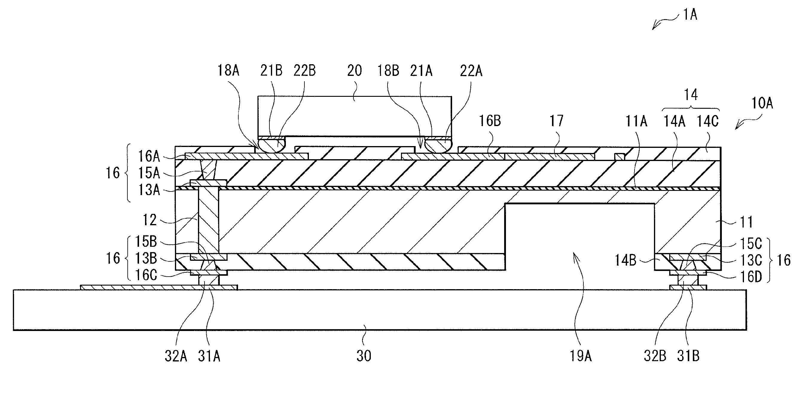
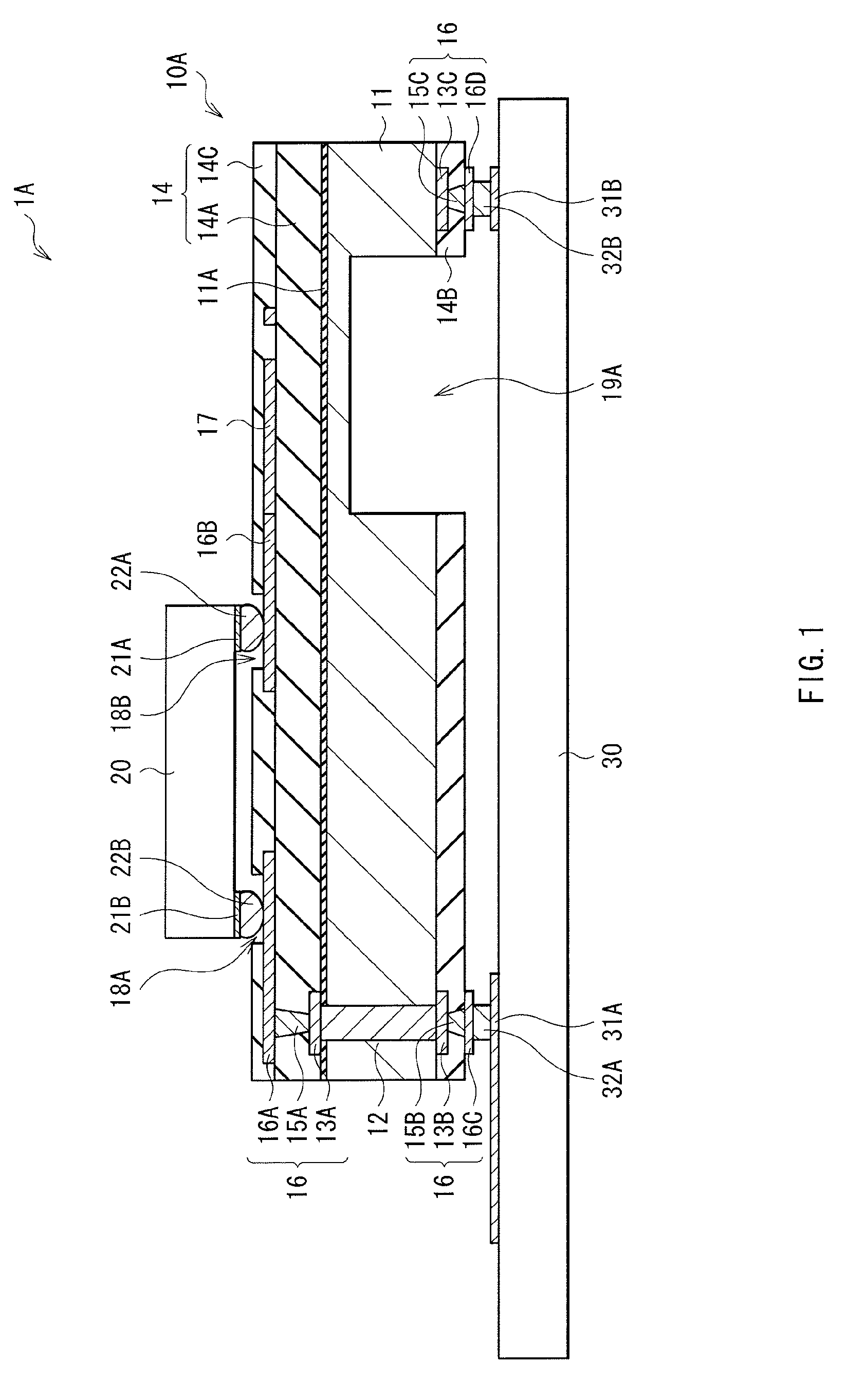
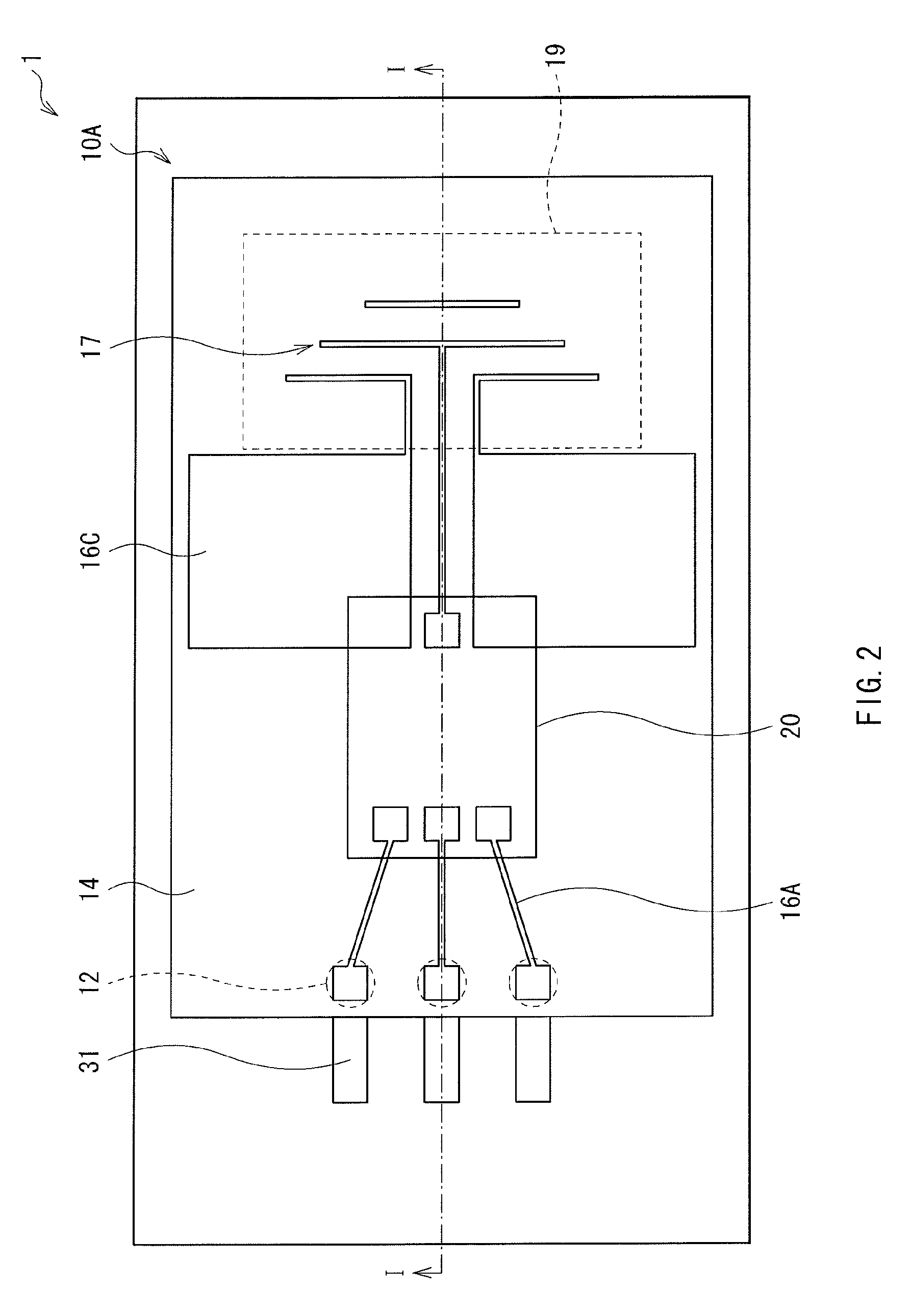
[0062]Next, a description will be given of an interposer 10C (10D) and a module 2A (2B) including the same according to a modified example of the interposer 10A (10B) and the module 1A (1B) including the same according to the foregoing embodiment. FIG. 11 illustrates a cross sectional structure of the module 2A including the interposer 10C having the concave section 19A in the substrate 11, and FIG. 12 illustrates a planar structure thereof FIG. 13 illustrates a cross sectional structure of the module 2B including the interposer 10D having the aperture 19B in the substrate 11. FIG. 11 and FIG. 13 are a cross sectional structure taken along line II-II of FIG. 12. For the same elements as those of the first embodiment, the same referential symbols are affixed thereto and the descriptions thereof will be omitted.

[0063]The interposer 10C (10D) connects the wiring layer 16 to the printed board 30 with a wiring 33. On the substrate 11, a chip-use connection section 23 is provided together...

application example

[0065]Next, a description will be given with reference to FIG. 14 of a configuration of a communication apparatus in which the interposer 10A of the embodiment of the invention is used. FIG. 14 illustrates a block configuration of the communication apparatus as an electronics device.

[0066]Examples of the communication apparatus illustrated in FIG. 14 include a mobile phone, a personal digital assistant (PDA), and a wireless LAN apparatus. For example, as illustrated in FIG. 14, the communication apparatus includes a transmission circuit 300A (module), a receiving circuit 300B (module), a transmitting / receiving switch 301 for switching the transmitting / receiving route, a high frequency filter 302, and a transmitting / receiving antenna 303.

[0067]The transmission circuit 300A includes two digital / analog converters (DAC) 311I and 311Q, and two bandpass filters 312I and 312Q that respectively correspond to transmission data of I channel and transmission data of Q channel, a modulator 320,...


PUM


Abstract

An interposer with which the manufacturing steps are able to be simplified and which shows superior high frequency characteristics is provided. The interposer includes: a substrate having a front face and a rear face; a wiring that is formed on the front face side of the substrate and is electrically connected to a semiconductor chip; an electric device connected to the wiring; and a concave section that is formed from the rear face side of the substrate in a position corresponding to the electric device.

Description

BACKGROUND OF THE INVENTION[0001]1. Field of the Invention[0002]The present invention relates to an interposer for intermediating electric connection and mechanical connection among a plurality of electronic devices with each wiring rule different from each other, a module, and an electronics device including the same.[0003]2. Description of the Related Art[0004]There is a single-digit or more gap between a pad pitch of a semiconductor chip whose miniaturization has been rapidly improved and a pad pitch of a substrate (mount substrate) on which the semiconductor chip is mounted. Such a gap leads to difficulty to reflect high performance obtained by progress of semiconductor technology and performance of a high function chip to a device or a system. For example, the practically used pad pitch of the semiconductor chip has been improved to 50 μm or less, while the pad pitch of the mount substrate (for example, a Print Circuit Board (PCB)) is about 500 μm. It is expected that miniaturi...

Claims


Application Information

Patent Timeline
Patent Type & Authority Applications(United States)
IPC IPC(8): H05K7/02
CPCH01L24/06H01L2223/6616H01L2223/6627H01L2223/6677H01L2224/05624H01L2224/05647H01L2224/45124H01L2224/45144H01L2224/48227H01L2224/49171H01L2924/01013H01L2924/01014H01L2924/01022H01L2924/01029H01L2924/01033H01L2924/01078H01L2924/01079H01L2924/014H01L2924/09701H01L2924/10253H01L2924/10271H01L2924/10272H01L2924/10329H01L2924/12044H01L2924/14H01L2924/15159H01L2924/15311H01L2924/1532H01L2924/1903H01L2924/19041H01L2924/19105H01L2924/3011H01Q1/38H01Q19/24H01Q19/30H05K1/024H05K1/141H05K1/16H05K2201/0191H05K2201/09036H05K2201/10674H01L23/13H01L23/147H01L23/645H01L23/66H01L24/48H01L24/49H01L2924/01006H01L2924/01019H01L2924/0105H01L2924/1515H01L2924/157H01L2224/48724H01L2224/48747H01L2224/48624H01L2224/48647H01L2224/16225H01L2924/30107H01L2224/0401H01L2924/1461H01L2924/00014H01L2924/00H01L24/45H01L2224/45015H01L2924/12034H01L2924/30111H01L2924/20752
Inventor AKIBA, AKIRAMITARAI, SHUNIKEDA, KOICHIMORITA, SHINYA
Owner SONY CORP
Why Eureka
Try Eureka